
Radio Spectrum Monitor

The project involves the development of a spectrum monitoring system for radio frequencies, utilizing an Atmel AVR microcontroller. The core functionality of this system is based on the Fast Fourier Transform (FFT) algorithm, which allows for the analysis of the frequency components of an input signal. The AVR microcontroller is selected due to its efficiency and capability in handling real-time signal processing tasks.
The circuit design typically includes an RF front-end that captures the radio frequency signals. This front-end may consist of components such as RF amplifiers, mixers, and filters to ensure that the desired frequency range is isolated and adequately amplified for processing. Following the RF front-end, an Analog-to-Digital Converter (ADC) is employed to digitize the analog RF signals, enabling the microcontroller to perform FFT analysis.
The FFT algorithm converts the time-domain signal into its frequency-domain representation, allowing for the identification of spectral patterns. The output of the FFT can be visualized using a graphical display or transmitted to a computer for further analysis. The system may also include user interface elements, such as buttons or a touchscreen, to allow users to configure parameters such as frequency range and sampling rate.
Challenges in this project may arise from factors such as noise interference, bandwidth limitations, and the need for precise calibration of the RF front-end components. Additionally, ensuring that the ADC operates within the required sampling rates to accurately capture the input signal is crucial for effective FFT processing.
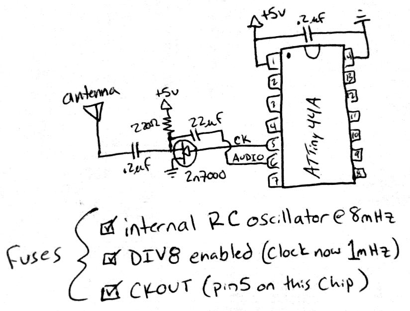
Overall, this spectrum monitoring system represents a complex integration of hardware and software, aimed at providing real-time analysis of radio frequency signals, with applications in various fields such as telecommunications, broadcasting, and electronic warfare.This is an experimental work to monitor a spectrum pattern of radio band, and is a continuous project from Audio Spectrum Monitor. To analyze the spectrum of an input signal, I chose an Atmel`s AVR microcontroller used in Audio Spectrum Monitor to process FFT.
When think it easy, it can be thought that sample an input RF signal directly and analyze it will do. However, you will able to recoginize that there are some techinical difficulties from following reasons.
🔗 External reference
Related Circuits
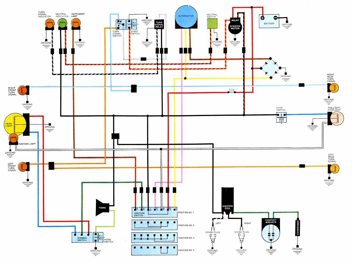
2012 Honda Odyssey Radio Wiring Diagram Manual PDF Download. The 2012 Honda Odyssey Radio Wiring Diagram Manual provides a detailed schematic of the audio system's wiring configuration for the vehicle. This manual is essential for understanding the connections and functionalities...
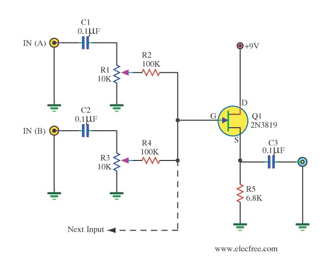
The audio from each radio will be connected to the iPod audio output and vice versa. This setup alters the impedance and can affect sound levels, potentially damaging the audio circuits of one or more radios involved. It is...
This circuit functions as a missing pulse detector, utilized in the General Purpose Controller Board with Basic Stamp 1. It monitors an input pulse train, and when a pulse is missed, the output of the 555 timer switches to...
This is a remote control circuit that uses radio frequency electrical signals to control a variety of applications. Component: Transistor. The remote control circuit operates by transmitting radio frequency (RF) signals to communicate with various devices. At its core, the...
Create a rapid transmitter/receiver pair that can be found in most households. An AM or FM radio system is suitable since it is widely accessible. The design focuses on generating the required radio signal and modulating it effectively. After...
Figure A illustrates the circuit of a direct-trigger timing light. The trigger voltage is obtained from the vehicle's ignition circuit via a direct connection to a spark plug. Figure B depicts a circuit utilizing an inductive pickup. A trigger...