
Liquid level and temperature monitoring circuit diagrams

The described circuit operates effectively to maintain and monitor liquid temperatures and levels through a combination of thermal sensing and relay control. The thermistor (K273) serves as the primary temperature sensor, detecting when the liquid reaches the set temperature of 95 degrees Celsius. Upon reaching this threshold, the thermistor's resistance changes, triggering the differential amplifier to send a signal to the relay. The relay, when activated, allows current to flow to the heating element, ensuring that the liquid is heated efficiently.
In terms of liquid level monitoring, the circuit employs two electrodes that are placed within the liquid. These electrodes act as a level sensor, detecting the presence or absence of liquid. The differential amplifier processes the signals from the electrodes to determine the liquid level accurately. When the liquid level falls below a pre-defined minimum, the circuit can be designed to activate the relay, allowing more liquid to flow into the container. Conversely, when the liquid level reaches the desired maximum, the additional relay contact can be engaged to stop the supply of liquid, thus maintaining a constant level.
The circuit's technical specifications highlight its versatility and reliability. Operating at a voltage of 15V ensures compatibility with standard power supplies, while the adjustable temperature setting allows for customization based on specific application requirements. The tolerance for voltage fluctuations and the specified temperature range further enhance the circuit's robustness in various environmental conditions. The temperature deviation of 1 degree Celsius provides a precise control mechanism, ensuring that the system reacts promptly to any changes in temperature or liquid level.
Overall, this circuit design is suitable for applications requiring precise temperature and liquid level management, making it ideal for use in industrial processes, laboratory settings, or any scenario where liquid heating and monitoring are critical. Circuit, if the thermistor K273 temperature reaches the setting level or not two sensor electrodes immersed in liquid, so that it is heated by turning on the relay. This ensure s that, when the heating is turned on there is always a minimum amount of liquid in the container. The circuit can also be used to monitor other liquid level. As shown in the level sensor is connected to the differential amplifier 1, the use of additional relay contact can be made to stop the supply of the liquid when the liquid level reaches the required so as to maintain the liquid level constant. Technical data: Operating voltage: 15V adjustable temperature: 95 degrees Celsius at 25.60 or voltage fluctuations (-15 ~ + 10%) and temperature (0 to 70 degrees Celsius) temperature deviation: 1 degree Celsius.
Related Circuits
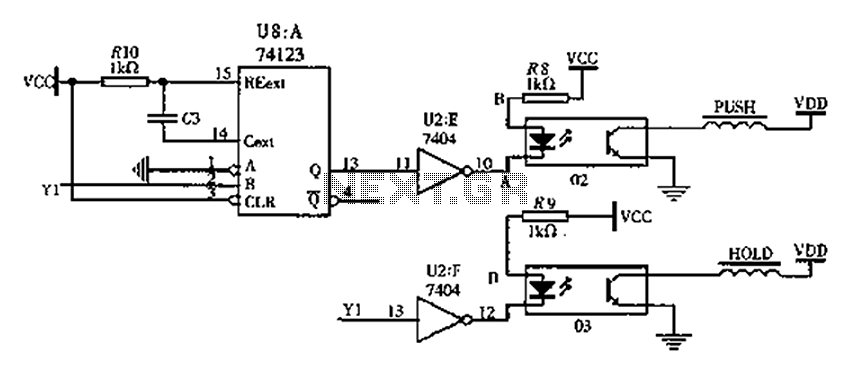
The FIG switching solenoid driver circuit utilizes the 74123 device chip (U8) and solid-state relays (02, 03). The switching electromagnet coil is referred to as the PUSH coil, while the HOL is maintained at a power supply voltage (VDD)...
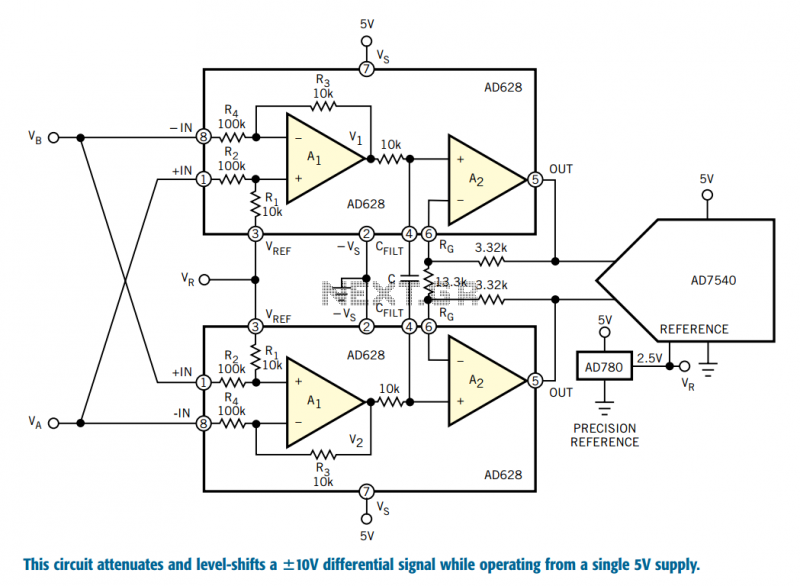
Designers who build equipment for the industrial market share a widespread problem. At one extreme, they must build equipment that supports ±10V bipolar voltages, often riding on a high common-mode level, a requirement enforced by 30 years of legacy...
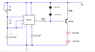
A TV remote jammer circuit using the NE555 timer IC. This device allows users to watch their favorite TV channels without interruptions, as it prevents others from changing the channel using a remote control when the circuit is activated....
The ZN414 integrated circuit (IC) contains a complete automatic gain controlled AM receiver within a compact three-pin package. With only a few external components, it is possible to construct a simple radio that offers excellent selection and reception capabilities....
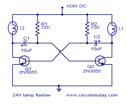
The circuit operates on 24V DC and is designed to alternately flash two 24V bulbs. It functions as an astable multivibrator with a frequency of 1Hz and a duty cycle of 50%. The lamps to be flashed are connected...
The system primarily consists of a permanent magnet disk, an integrated Hall sensor, a strobe gate, time base signal circuits, a power counting circuit, and a digital display circuit. The counting and digital display circuit utilizes the CMOS-LED digital...