
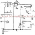
Switching solenoid drive circuit diagram

The circuit design involves several key components and their interactions. The 74123 monostable multivibrator (U8) serves as the primary control element, generating a pulse output when triggered by the input signal at pin Y1. The output pulse duration (T) is critical for ensuring that the switching solenoid operates effectively without overheating. The values of R10 (1000 ohms) and C3 (1000 microfarads) are chosen to achieve the necessary timing characteristics, allowing for a pulse width of 1 second.
The solid-state relays (SSR 02 and 03) act as electronic switches that control the high current flowing through the PUSH coil. When the output from the 74123 is activated, the SSRs conduct, allowing current to flow through the electromagnet coil, generating a magnetic field strong enough to actuate the solenoid. The use of solid-state relays enhances the reliability and efficiency of the circuit, as they provide faster switching times and longer lifespans compared to traditional mechanical relays.
The inverter (7404) inverts the output signal from the 74123, ensuring that the solid-state relay is activated correctly during the pulse duration. The design must consider the load characteristics of the solenoid, as the electromagnetic force generated must be sufficient to overcome any opposing forces, such as the return spring.
Overall, this circuit provides a robust solution for controlling solenoids in applications requiring precise timing and reliable operation, such as in dual-fuel systems or automated machinery. Proper selection of components and careful attention to timing parameters are essential for optimal performance and longevity of the circuit.FIG switching solenoid driver circuit, wherein the device chip U8 is 74123, the device is a solid state relays 02, 03, the switching electromagnet coil is sucked PUSH coil, HOL D is maintaining its coil power supply VDD to 24V. Of course, when the switching mechanism to switch to dual-fuel operation, from the B input pin Y1 74123 from the low to the high jump, fans variations make the output of 74123 Q output of a transient high current pulse, duration of T. After the inverter 7404, the potential of UA A low point will appear the same width, the solid state relay input terminal 02 also has a current time by T, then solid state relay output 02 appears conduction time T.
During this time, a strong suction current through the switching electromagnet coil inhalation, inhalation generate sufficient electromagnetic force of the electromagnet core. Pulse width T choice should refer solenoid switch setting performance parameters necessary to meet the core requirements of inhalation, can not be too long cause the coil to burn.
T is by selecting values of resistor R10 and capacitor C3 is determined. The Department T takes 1 second, R10 1000, C3 1000 F. Speaking from the mechanism, the switch and the solenoid to maintain the current high-voltage gas solenoid operating current is the same mechanism: when Y1 1, the existence of the holding current, the iron core is maintained at the suction state; when Y1 0 when no holding current exists, to restore the original core extended position under the action of the return spring.
Related Circuits
This charger is based on a charging voltage of 2.4 volts per cell, in accordance with most manufacturers' recommendations. This circuit pulses the battery with 14.4 volts (6 cells x 2.4 volts per cell) at a rate of 120...
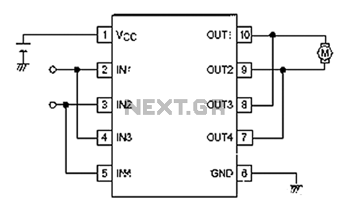
A simple motor control project for forward and backward drive can be implemented using the LB1948M motor driver IC, which features two channels for motor control. The LB1948M is an ideal choice for 12V motor drive systems and can...
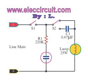
This is an automatic light dimmer circuit that eliminates the need for manual adjustment of light levels. It utilizes a Light Dependent Resistor (LDR) to detect ambient light conditions, which in turn controls a Triac to adjust the brightness...
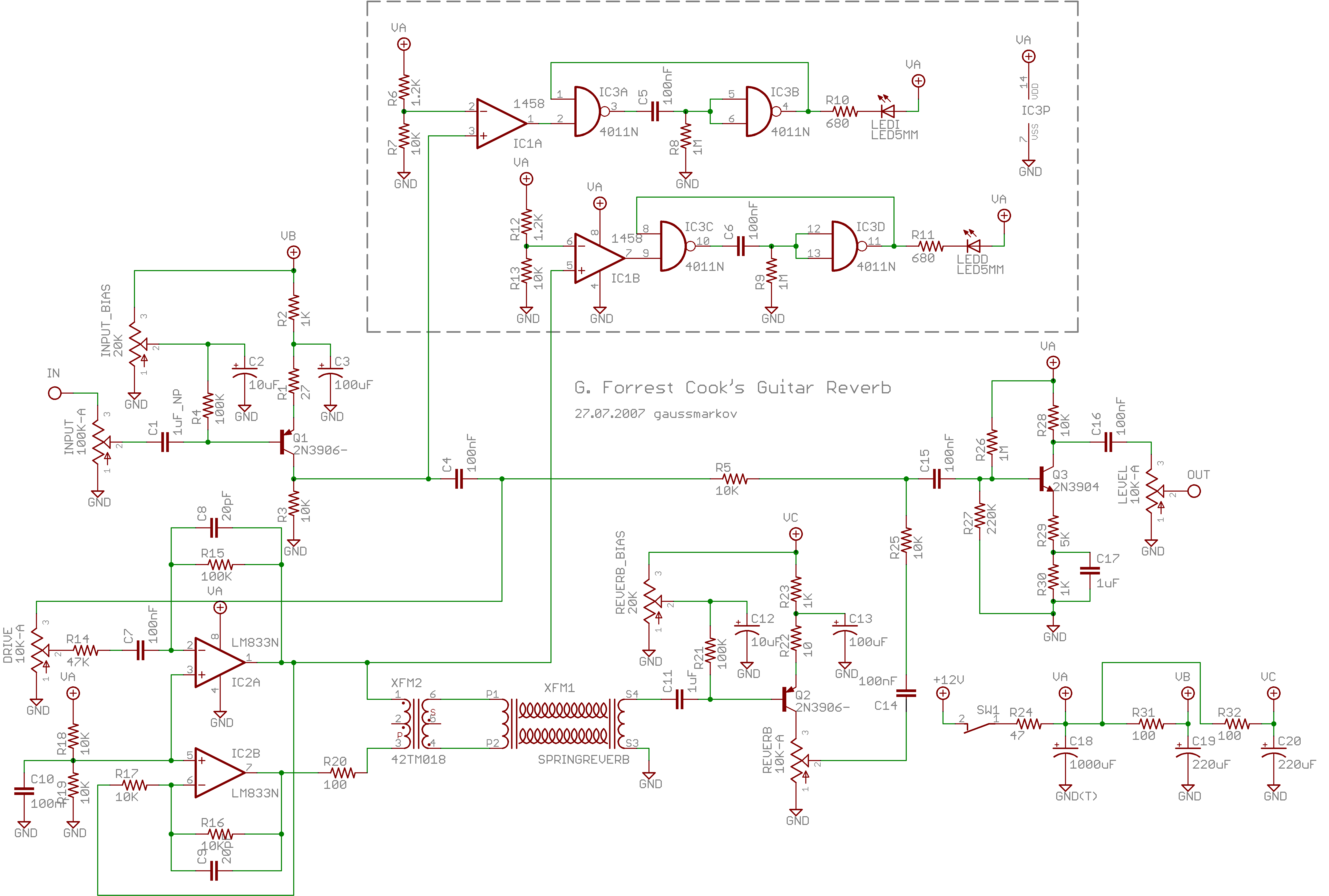
Spring reverb produces a clean and natural sound, often perceived as exceptionally good for a spring reverb. However, when the reverb springs are struck forcefully, they create explosive dub-like effects. Spring reverb is an analog sound processing technique that utilizes...
A basic circuit of the 89C2051 shown here can be made easily using point-to-point soldering with a universal PCB. Use an ordinary 20-pin socket, do not use a circle-pin socket. D1 is a small dot LED. U2 can be...
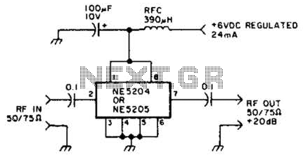
The Signetics NE5204 or NE5205 can be utilized in this audio frequency to 350-MHz (-30 dB) preamplifier. For a requirement of 600 MHz at 3 dB, the NE5205 should be employed. The noise figure is 4.8 dB at 75...