
Liquid level controller circuit diagram 1 -

The liquid level controller circuit is designed to monitor and manage the liquid levels within a specified container, ensuring that the levels remain within predetermined thresholds. The power supply circuit is essential for providing the necessary voltage and current to the entire system. It begins with a power switch (S1) that allows the user to turn the circuit on or off. The power transformer (T) steps down the voltage from the mains supply to a lower voltage suitable for the circuit operation.
The bridge rectifiers (UR1 and UR2) convert the alternating current (AC) output from the transformer into direct current (DC), which is then smoothed by the filter capacitors (C1 and C2). These capacitors help to reduce voltage ripple, ensuring a stable DC voltage is supplied to the control circuit.
The level detection control circuit plays a critical role in sensing the liquid level. It utilizes test electrodes (labeled a to c) that are placed at various heights within the container. These electrodes detect the presence or absence of liquid and send corresponding signals to the control unit. The control unit processes these signals to determine if the liquid level is above or below the set points. If the liquid level falls below a certain threshold, the control circuit can activate a pump or valve to refill the container, or if it rises above the maximum level, it can activate a drain mechanism.
This circuit can be further enhanced with additional features such as visual indicators (LEDs) to show the status of the liquid level, alarms for low or high levels, and even remote monitoring capabilities using wireless communication modules. The implementation of microcontrollers can also provide more sophisticated control algorithms, allowing for greater flexibility and accuracy in managing liquid levels. Overall, the liquid level controller circuit is a vital component in various applications, including industrial processes, water treatment facilities, and home automation systems.The liquid level controller circuit consists of the power supply circuit and level detection control circuit, and it is shown as the chart. Power supply circuit consists of the power switch S1, power transformer T, bridge rectifiers UR1, UR2 and filter capacitors C1, C2.
Liquid level detection control circuit is composed of the test electrodes a ~ c, control.. 🔗 External reference
Related Circuits
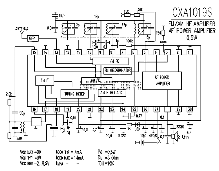
CXA1019 is a high-performance, high-sensitivity FM/AM radio special manifold developed by Sony, Japan. The CXA1019 features high integration, which includes an FM/AM tuner circuit, a mixer circuit, a mute circuit, an amplifier circuit (power output of 0.5 to 1W),...
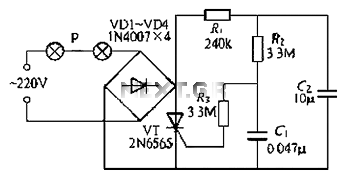
A simple and easy-to-implement one-way flashing lights string controller is designed for small shop or home decoration. This device utilizes a thyristor-based dimmer circuit, which operates effectively by managing large capacitance. The circuit includes a ten-microfarad capacitor connected to...
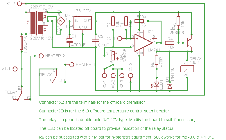
Affordable, straightforward, and precise thermostat circuits with instructions. The thermostat circuit is designed to provide a cost-effective and reliable solution for temperature control applications. It typically utilizes a temperature sensor, such as a thermistor or a thermocouple, to monitor the...
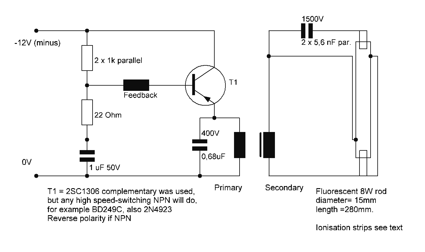
Starting a fluorescent lamp on an inverter can be challenging due to the trade-offs involved in achieving optimal operating efficiency with 12V drivers. Fluorescent lamps require a specific starting voltage to ionize the gas within the tube and initiate the...
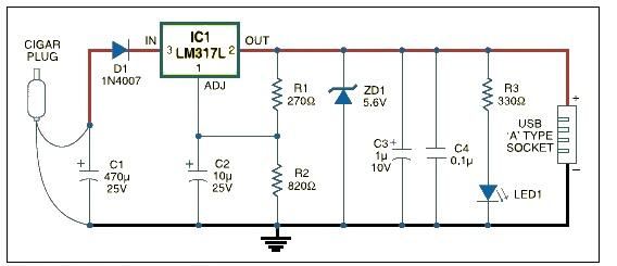
This USB car charger adapter project functions as a DC-DC power converter that effectively converts the 12V car battery voltage into a stable 5V output. It is designed to supply power from a car's cigar lighter socket to any...
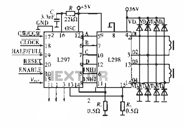
The circuit operates using a dedicated stepping motor controller, the L297. Pin 17 (CW/CCW) is utilized to control the rotation direction of the stepper motor. Pin 18 (CLOCK) regulates the speed of the stepper motor, while pin 19 (HALF/FULL)...