
Thermostat Circuits

The thermostat circuit is designed to provide a cost-effective and reliable solution for temperature control applications. It typically utilizes a temperature sensor, such as a thermistor or a thermocouple, to monitor the ambient temperature. The output from the temperature sensor is fed into a comparator circuit, which compares the measured temperature against a predetermined setpoint.
When the measured temperature deviates from the setpoint, the comparator activates a control mechanism, which can be a relay or a solid-state switch, to either engage or disengage a heating or cooling element. This feedback loop ensures that the temperature is maintained within a specified range, enhancing energy efficiency and comfort.
The simplicity of the circuit design allows for easy assembly and troubleshooting, making it suitable for both hobbyists and professionals. Additionally, the use of low-cost components ensures that the overall expense remains minimal while still achieving high accuracy in temperature regulation.
For implementation, a basic schematic would include the following components: a power supply, a temperature sensor, an operational amplifier configured as a comparator, a relay or transistor for controlling the load, and passive components such as resistors and capacitors to stabilize the circuit. Proper calibration of the temperature sensor and the comparator is essential for optimal performance, ensuring that the thermostat responds accurately to changes in temperature.
This type of thermostat circuit can be applied in various settings, including home heating systems, refrigeration units, and industrial temperature control systems, providing versatility and reliability in temperature management.Cheap, simple, and accurate thermostat circuits with instructions.. 🔗 External reference
Related Circuits
The AM transmitter circuit consists of an audio amplifier and an RF oscillator. The oscillator is constructed around transistor Q1 and its associated components. The tank circuit, which includes inductor L1 and variable capacitor VC1, is tunable from approximately...
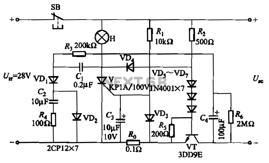
Capacitor C3 is used to determine the cutoff power, specifically the voltage threshold (VT cutoff), which influences the delay time selection. The schematic includes a reset button, SB, that is utilized to reset the system after a failure has...
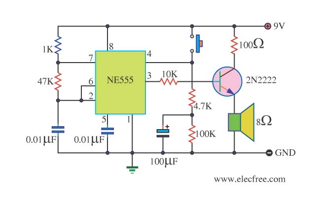
This is a danger beep circuit. It uses a 555 integrated circuit configured as a stable multivibrator that provides a duty cycle of 5% to drive a loudspeaker. The danger beep circuit utilizes the 555 timer IC, a versatile and...
High Power Siren Circuit. This article discusses a robust siren circuit suitable for various applications. A complementary transistor pair (BC557 & BC337) is configured as an oscillator to directly drive the speaker. Transistor Q1 (BC557) is utilized to ensure...
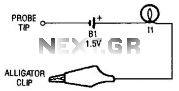
The continuity tester consists of a battery and a lamp connected in series, with one end of the circuit terminated with an alligator clip and the other end connected to the probe tip. The continuity tester is a fundamental...

Digital Command Control (DCC) provides significant advantages over traditional DC analog control systems, primarily due to its simplified wiring. DCC enables the individual control of multiple locomotives on the layout without requiring electrical isolation of track sections. The main...