
Lithium battery charging constant current circuit diagram

The lithium battery charging control board is designed to manage the charging process of lithium batteries efficiently. The heart of the circuit is the combination of a precision adjustable voltage regulator and an adjustable constant current circuit. The TL431 component acts as a voltage reference, enabling accurate regulation of the output voltage. The transistor Q1 functions as a pass element in the voltage regulation path, allowing for adjustments based on the feedback received from the battery voltage.
The adjustable constant current circuit, comprised of Q2, W2, and R2, ensures that the charging current remains stable and adjustable, which is critical for the safe charging of lithium batteries. This circuit prevents overcurrent conditions that could damage the battery during the charging phase.
The charging indicator circuit is crucial for providing visual feedback regarding the charging status. The LED, controlled by Q3, lights up during the charging process. The resistors R3, R4, and R5 are configured to ensure that the LED operates within its specifications and provides a clear indication of the charging state. As the battery charges and reaches its voltage threshold, the current flowing through R4 decreases, ultimately leading to the turn-off of Q3 and the LED.
Once the battery is fully charged, it is recommended to continue the charging process for an additional 1 to 2 hours to ensure that the battery is adequately conditioned. This practice helps to enhance the longevity and performance of the lithium battery. Furthermore, proper thermal management is essential; therefore, installing heat sinks on Q2 and Q3 is necessary to dissipate heat generated during operation, ensuring that the components operate within safe temperature limits.
This circuit design exemplifies a robust solution for lithium battery charging, integrating precision voltage regulation, current control, and effective charging status indication, all of which are vital for maintaining battery health and performance. As shown in FIG lithium battery is a constant current charging control board, the figure Q1, R1, W1, TL431 composition precision adjustable voltage regulator circuit. Q2, W2, R 2 constitute an adjustable constant current circuit. Q3, R3, R4, R5, LED charging indicator circuit. With a rechargeable lithium battery voltage is gradually increased, the charging current will gradually decrease, decreasing the voltage drop on R4 After the battery is fully charged, and ultimately ended Q3, LED goes out, the battery can in order to ensure adequate, please extinguish lights after 1 to 2 hours to continue to charge, the need Q2, Q3 appropriately sized heat sink mounted when used.
Related Circuits

Circuit characteristics: A simple phase shift range of 180 degrees, with a practical range of 170 degrees. The circuit is influenced by temperature and is suitable for small power applications in less demanding situations. The circuit operates by utilizing a...
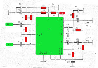
The amplifier circuit utilizes the STK integrated circuit, similar to a previous design. This circuit features two inputs and two outputs, commonly known as a stereo amplifier. It is a power amplifier rated at 2 x 18 Watts with...
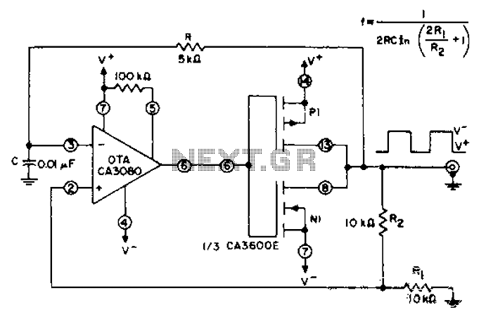
CA3600E array transistor pair and a reverse CA3080 operational amplifier are used together to provide precise timing and thresholds for the square wave. A typical static power consumption is 6mW. The CA3600E is a versatile integrated circuit that includes multiple...
This electronic circuit utilizes a 555 timer as the foundation for a touch switch. When the plate is touched, the 555 timer is activated, causing the output on pin 3 to go high, which turns on the LED and...
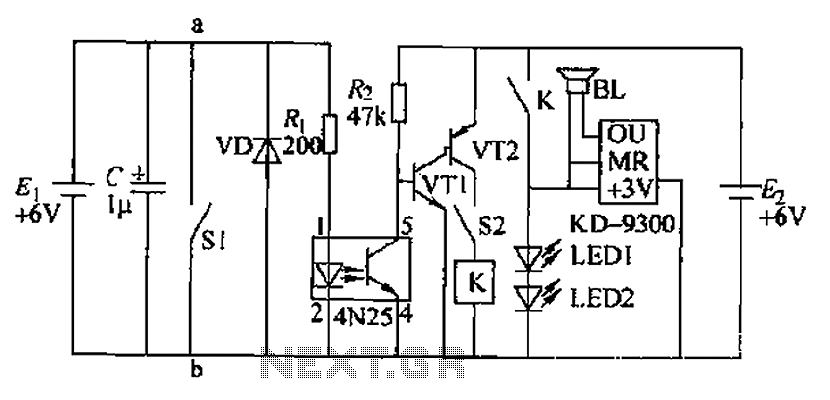
Due to the fast pace of modern life, intense competition, and widespread insomnia, which poses health risks, this section presents a feasible and effective method for controlling photoelectric hypnotic music to alleviate insomnia and facilitate sleep. The principle circuit...
This circuit was developed in response to requests from website visitors for a timer that can emit a beep after intervals of one, two, three minutes, and so forth, for jogging purposes. As depicted in the circuit diagram, SW1...