
LM/MW converter for ham-only receivers

The circuit schematic is designed to adapt vintage ham band receivers for broader frequency coverage, facilitating the reception of various broadcast bands. The integration of untuned bandpass filters allows for selective frequency filtering, while the MOSFET mixer ensures efficient signal processing. The use of crystal oscillators provides stable frequency generation, crucial for maintaining signal integrity across the selected bands. The band-selector switch simplifies operation, allowing users to easily switch between different frequency ranges.
The filtering stages are critical for maintaining signal clarity, particularly in environments with potential interference from other transmitters. The implementation of low-pass and high-pass filters ensures that unwanted frequencies are attenuated, thereby enhancing the overall performance of the receiver. The choice of design impedance at 120 ohms is a practical consideration, as it allows for compatibility with a variety of signal sources without significant degradation of the passband characteristics.
Overall, this circuit design exemplifies a practical approach to modernizing older receiver technology, enhancing their capabilities while preserving the original functionality. The careful selection of components and filter configurations ensures optimal performance across a wide range of frequencies, making it a valuable addition to any amateur radio setup.Before the advent of broadband communications receivers with synthesized oscillators, high-grade, hamband receivers used crystal oscillators and a variable IF to cover relatively narrow (500-600 kHz) frequency segments. The schematic shows a circuit that will adapt most of these receivers to cover the long-wave (150-400 kHz), standard (520-1600 kH
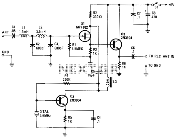
z), and tropical (2. 2-2. 4 and 3. 2-3. 4 MHz) broadcast bands, plus all of the other interesting stations in the 0. 1-1. 6 and 2. 0-3. 6 MHz frequency ranges ( Fig. 1 ). The circuit consists of untuned bandpass filters, a MOSFET mixer, and a crystal oscillator. The only control is the band-selector switch. The actual tuning is done with the receiver itself (acting as a variable-frequency IF amplifier). Only three crystals are needed for six bands because the 80-meter ham band is used as a difference IF for the LW and MW bands, and the 40-meter ham band is used as a sum IF for the short-wave bands. When one of the LW/MW bands is selected, a two-section low-pass filter with a 2. 2-MHz corner is inserted to eliminate IF pickup, image frequencies, and to prevent overload by nearby shortwave transmitters.
When one of the short-wave bands is selected, a two-section high-pass filter with a 1. 8-MHz corner and a two-section low-pass filter with a 4. 3-MHz corner are inserted for similar reasons. The design impedance for these filters is approximately 1200 ©, so the component values are highly practical, and any mismatch in the driving source will not affect the passband shape. The mismatch at the output of the filters was found to improve the corners. The frequency ranges mentioned above and in the chart (Fig. 1, again) are for a receiver with 600-kHz segments. If your receiver uses 500-kHz segments, coverage of the standard broadcast band is limited to 1500 kHz.
The obvious remedy is to add a 5. 5-MHz crystal. The capacitors in series with the crystals are a means of excitation control. In the unit shown, they ranged from 20 to 62 pF; the values used should produce approximately 3-Vrms oscillator output voltage. This voltage is applied to the mixer`s injection gate through a low-pass filter to eliminate oscillator harmonics.
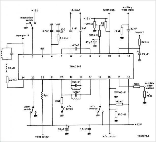
An emitter-follower with a voltage divider reduces both the mixer output level and its impedance to values suitable for a hot receiver. If higher output is needed, replace the resistive divider with a transformer output ( Fig. 2 ). The input impedance of the circuit is 75 ©, so it must be driven by a lowimpedance signal source. A loop antenna with a 75- © output (see High-Frequency Loop Antenna, Electronic Design, July 22, 1996, p.
112) is the ideal signal source, since ferrite-rod loops can easily be constructed to provide coverage at the frequencies involved. 🔗 External reference
Related Circuits
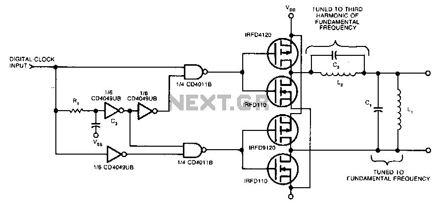
Two pairs of MOSFETs create a bridge that alternately switches current in opposite directions. Two parallel-resonant LC circuits complete the converter. The L1/C1 combination is resonant at the fundamental frequency, while the L2/C2 combination resonates at the third harmonic...
This voltage-to-frequency converter circuit features a voltage-controlled oscillator with a deviation of 0.5%. The integrated circuit IC1 functions as a multivibrator, generating rectangular impulses of equal width. The output frequency is adjustable via the U1 voltage. The D3 diode...
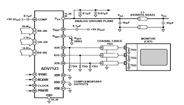
This digital-to-analog converter (DAC) integrated circuit is designed for optimal noise performance, minimizing both radiated and conducted noise. A recommended connection diagram for the ADV7123 is depicted in the following schematic diagram. According to the ADV7123 datasheet, this device...
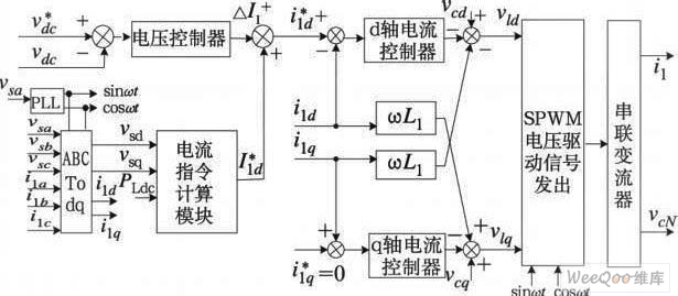
The demand for high-quality electric energy in modern industrial development is increasing, making it essential to provide safe and reliable green power to energy consumers. Uninterruptible Power Supplies (UPS) are crucial for improving electric energy quality and ensuring the...
The VLF Converter is designed to receive signals for general coverage in shortwave receivers. It can pick up various unusual signals on frequencies below 15 kHz. This converter effectively transforms frequencies ranging from 0 to 250 kHz into a...
The circuits utilize two FM Demodulator TDA2555 systems to execute the demodulation functions necessary in a dual sound carrier television system for demodulating the sound carriers. The distinction between the TDA2555 and TDA2557 lies in the number of stages...