
TDA2549 TDA2549 I.F. Amplifier And Demodulator For Multistandard TV Receivers

The circuit design incorporates two TDA2555 FM demodulator systems, which are essential for processing the audio signals in dual sound carrier television systems. Each TDA2555 unit is equipped with an eight-stage limiting amplifier, which enhances the signal-to-noise ratio and ensures that the demodulated audio is clear and free from distortion. In contrast, the TDA2557 features a five-stage limiting amplifier, which may be suitable for applications where a slightly lower level of signal processing is acceptable.
The quadrature demodulator integrated into the circuit is crucial for the detection of frequency modulation (FM) signals. It effectively demodulates the audio information from the FM carrier signals, allowing for high-fidelity sound reproduction. The de-emphasis stage that follows the demodulation process is designed to counteract the pre-emphasis applied during the transmission of the audio signal, thereby restoring the original audio quality.
Furthermore, the output amplifier provides the necessary gain to drive speakers or other audio output devices, ensuring that the demodulated signals are amplified to a suitable level for listening. Each FM demodulator is equipped with a mute function, which allows for the silencing of audio output during periods of no signal or when switching between audio channels. This feature enhances user experience by eliminating unwanted noise during transitions.
The overall design reflects a robust approach to FM audio demodulation in television systems, with careful consideration given to signal integrity, user control, and compatibility with existing television broadcasting standards. The use of TDA2555 and TDA2557 components from NXP Semiconductors underscores the reliability and performance of the circuit in delivering high-quality audio output.The circuits incorporate two FM Demodulator TDA2555 systems to perform the Demodulator functions required in a dual sound Carrier TV system for demodulating the sound Carriers The difference between TDA2555 and TDA2557 is the number of stages of the Limiting Amplifier Eight TDA2555 or five (TDA2557) stage Limiting Amplifier Quadrature Demodulator for FM detection De-emphasis stage Output Amplifier Mute function for each FM demodulato By NXP Semiconductors 🔗 External reference
Related Circuits
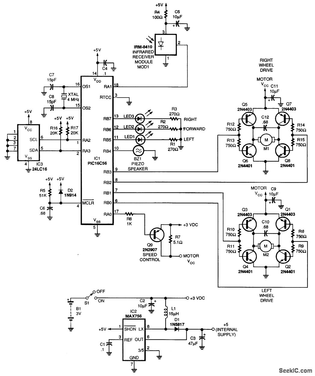
This article describes the Flip-Flop Flashers and Buzzers circuit utilizing the 2N4401 transistor. The content is straightforward and provides valuable insights. Components mentioned in this article can enhance the reader's understanding. For instance, the article includes information on where...
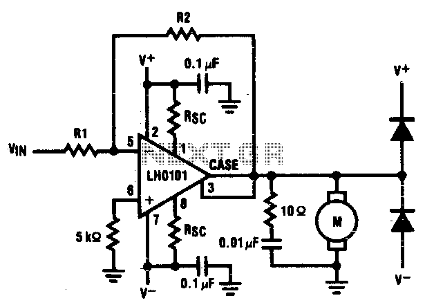
The motor driver amplifier is designed to deliver the rated current to the motor. It is important to manage power dissipation to remain within allowable limits. This precision speed regulation circuit utilizes rate feedback to maintain a constant motor...
This low-cost project allows audio reproduction from a TV without disturbing others. It eliminates the need for wired connections between the TV and loudspeakers by utilizing invisible infrared light to transmit audio signals. Without the use of lenses, a...
Here is an amplifier circuit based on the BUZ11, which can be replaced by an IRFZ34N, and an ECC83 can be used instead of the ECC88. In this case, the anode voltage should be reduced slightly to 155 V....
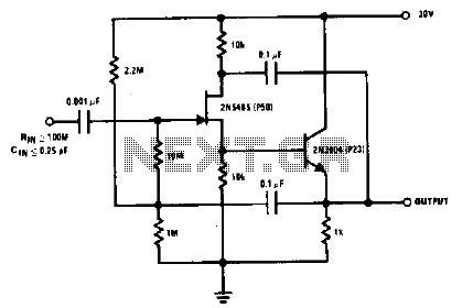
The 2N5485, which has a very low-capacity legacy, is always operated as a source follower with gate bias bootstrap. In this circuit, nothing is left to chance in reducing input capacitance. The 2N5485 is a JFET (Junction Field Effect Transistor)...

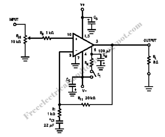
This is a simple headphone amplifier circuit designed to drive headphones when a music player lacks sufficient power. The circuit is straightforward and utilizes only three transistors. The first transistor, Q1 (BC 239), along with its associated components, functions...