
LM1893 for Power Line Modem Circuit

The LM1893 power line modem circuit is designed for efficient data communication over existing power lines, capitalizing on the infrastructure already in place. The LM1893 chip serves as the core of the design, facilitating the modulation and demodulation processes required for transmitting and receiving data. The half-duplex communication capability allows for bidirectional data flow, which is essential for applications that require feedback or acknowledgment from the receiving end.
To enhance the performance of the circuit, an impulse noise filter is employed. This filter mitigates the impact of electrical noise that may interfere with the data signals, ensuring a cleaner signal is received. The PLL-based demodulator further improves the reliability of the data transmission by accurately tracking the frequency of the incoming signal, allowing for better synchronization and decoding of the transmitted information.
The transmission process involves the generation of a sinusoidal carrier wave, which is modulated using frequency-shift keying (FSK). This modulation technique allows for the encoding of digital data onto the carrier wave by varying its frequency, making it suitable for transmission over the power line. The rugged on-chip driver of the LM1893 ensures that the modulated signal can be effectively transmitted across the power line, which may have varying impedance and noise characteristics.
The inclusion of a COPS controller and discrete components in the circuit design provides additional flexibility and functionality. The COPS controller can manage various operational parameters, enhancing the overall performance of the modem. Discrete components may include resistors, capacitors, and inductors that are tailored to optimize the circuit's response and reliability.
In summary, the LM1893 power line modem circuit is a sophisticated solution for data communication over power lines, incorporating advanced techniques such as FSK modulation, noise filtering, and PLL demodulation to ensure robust and reliable performance in diverse environments.This design circuit is shows an LM1893 power line modem circuit. This circuit is used to transfer information between remote locations by using the power mains. This circuit uses LM1893 that is used as a power line interface for half-duplex (bi-directional) communication of serial bit stream of virtually any coding. This is the figure of the circu it; To give maximum range, impulse noise filter and a PLL-based demodulator are combined in reception. In transmission, a sinusoidal carrier is impressed and FSK modulated on most any power line via rugged on-chip driver.
Besides LM1893, this circuit also uses a COPS controller and discrete components. [Circuit diagram source: National Semiconductor`s Application Note] 🔗 External reference
Related Circuits
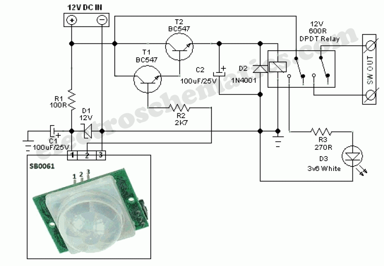
This circuit represents a general-purpose white LED security light equipped with a Passive Infrared (PIR) motion sensing mechanism. The core component of the circuit is the PIR sensor module SB0061, which is a pyroelectric sensor designed for human body...
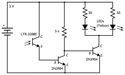
Here is an inexpensive electronic circuit that can be built to place in a Jack-o'-lantern. It provides power to drive a few LEDs at night and automatically turns them off during the daytime. This is a simple and automatic...
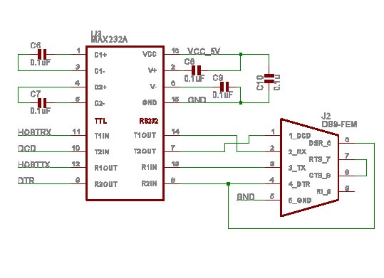
Despite the remarkable growth of wireless connections, analog POTS, or "plain old telephone service," continues to excel in terms of cost and availability. Credit card terminals and home security systems are two examples of older connected devices. However, the...
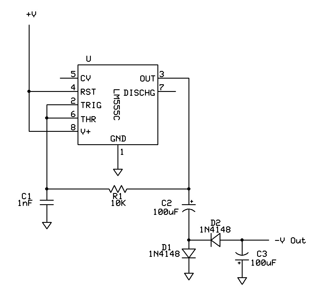
Can a 555 negative supply circuit, like the one below I pulled from another schematic, supply enough negative voltage to an LM324 and an AD736JN? The 555 timer integrated circuit can be configured to generate a negative voltage supply,...
A step-down transformer converts AC 220V to a lower voltage. A diode bridge rectifier and filter capacitor provide a direct current (DC) output, which fluctuates with variations in the grid voltage. A resistive voltage divider is used for sampling....
As shown in the generator start battery automatic monitor circuit diagram. The generator start battery automatic monitor circuit is designed to oversee the battery's status during generator operation. This circuit ensures that the battery remains charged and functional, preventing premature...