
555 circuit Can supply enough neg voltage

The 555 timer integrated circuit can be configured to generate a negative voltage supply, which can be utilized to power operational amplifiers such as the LM324 and the AD736JN. The operation of the 555 timer in this configuration typically involves using external components such as resistors and capacitors to establish the desired output voltage level.
In a standard negative voltage supply circuit using a 555 timer, the circuit is configured in astable or monostable mode to generate a square wave output. This output can then be fed into a charge pump or a voltage inverter circuit, which converts the positive voltage into a negative voltage. The LM324, a quad operational amplifier, requires a negative supply voltage for operation in certain configurations, particularly when dealing with bipolar input signals. Similarly, the AD736JN, which is a precision analog multiplier, also benefits from a dual supply configuration for optimal performance.
When designing the circuit, it is essential to consider the output current requirements of the LM324 and AD736JN to ensure that the 555 timer can provide sufficient current without overheating or failing. The voltage levels should be monitored and adjusted as necessary to meet the specifications of the components being powered. Additionally, proper decoupling capacitors should be used to stabilize the supply voltage and minimize noise in the circuit.
In conclusion, a 555 timer configured as a negative supply circuit can indeed supply the necessary negative voltage for the LM324 and AD736JN, provided that the circuit is designed with attention to the load requirements and stability considerations.Can a 555 negative supply circuit, like the one below I pulled from another schematic, supply enough negative voltage to a LM324 and a AD736JN? I`m.. 🔗 External reference
Related Circuits
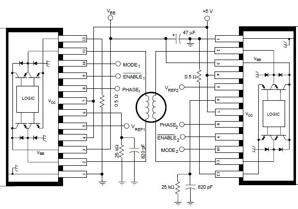
The A3952S stepper motor controller, designed by Allegro MicroSystems, can be utilized to create a straightforward and effective motor driver circuit suitable for various electronic applications. This controller supports continuous output currents of up to 2 A and operates...
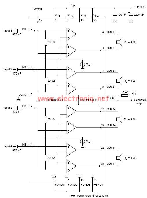
This electronic circuit diagram represents an audio power amplifier utilizing the TDA8571J integrated circuit. It is a class-B output amplifier configured in a BTL (Bridge-Tied Load) arrangement, featuring four amplifiers, each with a gain of 34 dB. The main...
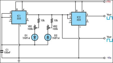
This timer utilizes two 555 integrated circuits (ICs) to adjust the desired output. The variable resistors VR1 and VR2 serve as potentiometers to modify the cycle speed. The circuit can be powered with a 9 to 12-volt power supply,...
Each zone uses a normally closed contact. These can be micro switches or standard alarm contacts (usually reed switches). Zone 1 is a timed zone which must be used as the entry and exit point of the building. Zones...
0.1V to 50V Variable Power Supply Circuit Diagram. Features: the lowest current limit is 0.6 ampere, opamp CA3130 compares the reference voltage. The variable power supply circuit is designed to provide an adjustable output voltage ranging from 0.1V to 50V,...
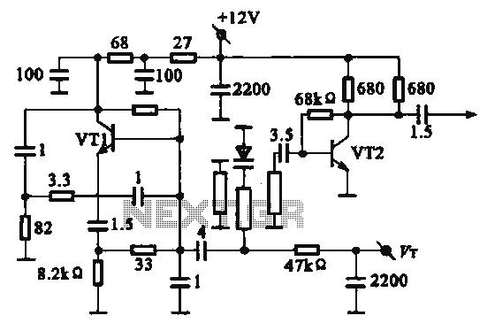
The local oscillator operates at frequencies of 1 GHz or higher, utilizing a common collector circuit, which makes it challenging to generate low-frequency self-oscillation. Typically, the local oscillator signal is passed through a buffer amplifier stage before being applied...