
LM2876 amplifier configuration

The LM2876 power amplifier circuit is a robust design intended for audio applications, featuring an integrated circuit that simplifies the amplification process while ensuring high fidelity. The use of an external transistor configured as an emitter follower allows for a stable output level, which is essential for maintaining audio quality. This configuration also aids in minimizing distortion and enhancing the linearity of the amplifier's response.
The mute switch (SA) is strategically placed within the circuit to allow for quick disengagement of the amplifier output, providing a means to silence the audio without altering the gain settings. This feature is particularly beneficial in scenarios where immediate silence is required, such as during interruptions or transitions between audio sources.
The potentiometer (RP) serves as a variable resistor, allowing the user to adjust the volume of the audio output. This component is critical for user interaction, providing a simple yet effective means to control sound levels according to the listener's preference.
Capacitor C4 plays a significant role in the overall performance of the amplifier. By connecting it to the AC ground, it acts as a filter that improves the common mode rejection ratio (CMRR). A higher CMRR indicates better performance in rejecting noise that may affect the audio signal, leading to clearer sound reproduction. The choice of a 7-foot capacitance value is specifically aimed at optimizing the frequency response and enhancing the amplifier's ability to handle various audio signals without introducing unwanted artifacts.
In summary, this power amplifier circuit design effectively integrates various components to ensure high-quality audio output while providing user-friendly features such as volume control and a mute function. The careful selection of components and their configuration is crucial for achieving optimal performance in audio applications.A single power amplifier circuit LM2876 crrL constituted. VTf external transistor to form the emitter type to provide neutral level (7 feet) for the LM2876, guaranteed lC relia ble noise suppression circuit and associated circuitry bias. Mute switch button switch SA. Potentiometer RP for the volume control. Capacitor C4 is 7 foot AC ground capacitance, the purpose is to improve the common mode rejection ratio of the amplifier, power amplifier to improve sound quality.
Related Circuits
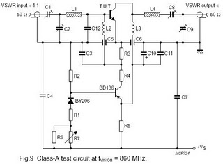
The circuit is designed for driving small UHF TV transmitters, providing a gain of 7 dB and capable of amplifying signals within the frequency range of 470-860 MHz. Key components include resistors, capacitors, and transistors. This circuit serves as a...
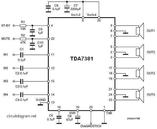
The TDA7381 is a Class AB audio power amplifier housed in a Flexiwatt25 package, specifically intended for car radio applications. This circuit can also be utilized for various other purposes. The fully complementary PNP/NPN output configuration enables a rail-to-rail...
The input stage is comprised of both halves of a 6SL7 octal dual hi-mu triode in a differential amp configuration with a 1mA constant current cathode load. Field-effect (constant-current) diodes are used for simplicity. The differential amp approach was...
The operational amplifier (op-amp) has a significant history, particularly with the 741/301 series, which has been popular for approximately 20 years due to its ease of calculation (gain calculation), affordability, and simplicity of construction. The versatility of op-amps allows...
A transistor optocoupler interface circuit, as described in section 15.1.6, has been implemented. This circuit serves as a transistor interface with other circuits. The transistor optocoupler interface circuit utilizes a light-emitting diode (LED) and a phototransistor to achieve electrical isolation...

This UHF wideband signal amplifier provides a total gain of 10 to 15 dB within the 400 - 850 MHz frequency range, making it suitable for applications where the television signal is weak. For optimal performance, the component pins...