
lm3914 in dot mode

The circuit described is a sophisticated electronic design that integrates multiple components to achieve precise measurements and visual indicators. The use of the LM3914 in dot mode allows for a clear, visual representation of the measurement values, making it user-friendly. The 555 timer, known for its versatility, operates in astable mode to generate a square wave signal, which is essential for the synchronous rectification process. This process is critical as it converts the AC signal from the measurement into a usable DC signal, which can then be amplified by the OP37 operational amplifier.
The OP37 is chosen for its low offset voltage, ensuring accurate amplification of small signals, which is particularly important in applications involving microvolt measurements. The differential amplifier configuration is optimal for minimizing noise and enhancing the signal-to-noise ratio, which is crucial in precision measurement applications.
The 2N2222 transistor acts as a current pump, providing the necessary drive to maintain stable operation of the circuit. Its placement above the OP37 indicates its role in powering the operational amplifier, ensuring that the amplifier receives adequate current for optimal performance.
The LM324 is utilized not only as an indicator but also as an analog-to-LED converter. This dual functionality allows the circuit to display the measured values visually, which is beneficial for quick assessments. The choice of gold-plated probes or solid gold pins enhances conductivity and reduces contact resistance, further improving measurement accuracy.
Overall, this circuit design exemplifies a well-thought-out approach to electronic measurement, combining various components to create a reliable and effective tool for troubleshooting and analysis. The attention to detail in selecting high-quality components reflects a commitment to precision and performance in electronic engineering.This indicates like LM3914 in dot-mode. It is a drawing i made made to troubleshoot a gadget, around two decades ago. Strangely it had a echo of a design i had made into a 7107 dpm years before that. Now i am scanning all my drawing and notes, useful or not. Clean or with errors. Many Errors = 1 Blunder. Some projects i made have been expensive Bl unders. So see them with a skeptic eye, fix them, try them. Thats all for now. This has a 9V battery power. The 555 spins and a negative voltage for Opamp is created. This is a Low Offset amp of OP37 of Precision Monolithics, Inc PMI an early innovator. This diff-amp amplifies the uV of a 4 wire resistance measurement. Now the current pump is the 2N2222 you see above the OP37. The FET and 555 do synchronous rectification. The LM324 is the Indicator and Analog to LED Dot-Bar Converter. The probes are Gold Plated, or use solid gold pins if you have them in plenty. 🔗 External reference
Related Circuits
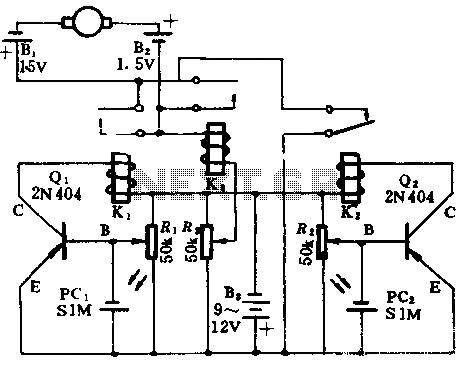
In the absence of light, photocells PC1 and PC2 exhibit high resistance, causing transistors Q1 and Q2 to remain off, which prevents the relay contacts K1 and K2 from closing. The battery B3 is connected through a potentiometer Rs,...
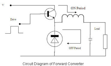
Switched Mode Power Supplies (SMPS) are categorized as DC to DC converters and DC to AC converters. Switched Mode Power Supplies (SMPS) are essential components in modern electronic devices, providing efficient power conversion from one form to another. The primary...
This simple circuit produces a loud trilling noise if no valid transmitter signal is received. This frequency must correspond with the resonant frequency of the piezo element; otherwise, the sound level will be very low. More: When you switch...
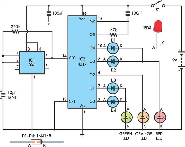
Children today often possess a wide array of toys available in stores. For those with a son or grandson who has a collection of toy cars, a handmade gift such as a set of traffic lights would be greatly...
It is possible to apply switch-mode techniques to a silicon CMOS semiconductor process to create a current-mode power amplifier with high gain and efficiency for use in 2.4-GHz wireless applications. Amplification at 2.4 GHz is essential for various wireless...
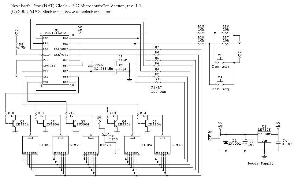
The schematic diagram and electronic assembly are relatively simple, as most of the functionality is managed by the microcontroller code. The schematic diagram serves as a visual representation of the electronic circuit, outlining the connections between various components such as...