
LM741 Ham Radio

The LM741 operational amplifier is a versatile component widely used in various analog applications, including ham radio circuits. This specific circuit diagram incorporates the LM741 to facilitate multiple functionalities such as amplitude modulation (AM), frequency modulation (FM), and single sideband (SSB) transmission at 7 MHz.
The design typically features a balanced mixer stage, which is essential for SSB operation, allowing the combination of two frequency signals while suppressing the carrier frequency. The inclusion of a dummy load is crucial for testing and ensuring the stability of the transmitter without radiating signals, which can interfere with other communications.
In addition to the basic transmission capabilities, the circuit may incorporate a frequency synthesizer module (FSM) to provide a stable and adjustable frequency output. This allows operators to select different frequencies within the ham radio bands, enhancing the transceiver's versatility.
The DSB (Double Sideband) transmitters are also an integral part of this circuit, enabling the transmission of information over a wider bandwidth, which is particularly useful in voice communications.
Overall, the LM741 ham radio circuit diagram serves as a foundational design for amateur radio enthusiasts, providing a comprehensive platform for experimenting with various modulation techniques and enhancing communication capabilities within the amateur radio spectrum.This circuit shows about LM741 Ham Radio Circuit Diagram. Features: including AM, FM, 7 MHz SSB Transceiver, FSM, Dummy load, DSB transmitters, .. 🔗 External reference
Related Circuits
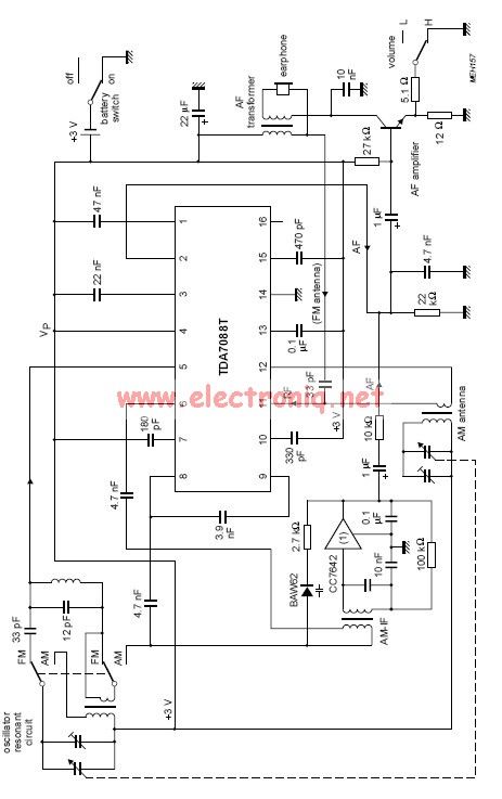
The TDA7088 incorporates a frequency-locked loop (FLL) system with an intermediate frequency (IF) of approximately 70 kHz. This circuit can be powered using a 3-volt battery cell or a regulated power supply. The TDA7088 is designed for use in various...
There has been a longstanding interest in constructing a simple VXO transmitter, though concerns regarding the limited tuning range typically associated with VXOs on busy HF bands have been present. The capability to switch between multiple crystals and cover...
Cal-(IT)2 is developing several generations of general broad application radio/networking test platforms for wireless research and development. CalRadio I is the first generation. It provides a simple, low-cost platform for 802.11b development from the MAC layer and up. It...
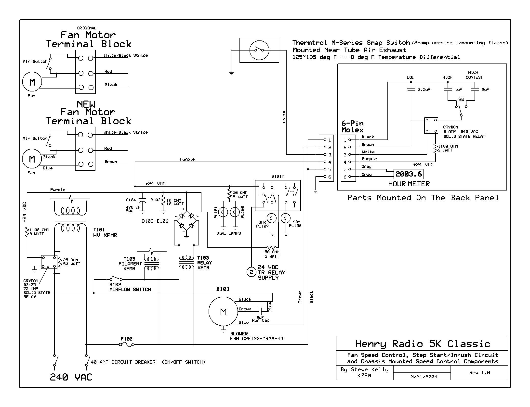
The back cover has been removed, revealing the upper deck of the power supplies and the original Dayton 2C915A blower (220VAC - 140CFM) mounted to the cabinet's underside. The RF deck enclosure has also been taken off. The upper...

The circuit consists of a radio remote lighting switch utilizing RCM1 type radio-controlled remote control transmitter and receiver components. It features the RCM1A/B component, which facilitates the remote control functionality. Additionally, the design incorporates a remote control transmitter and...
A schematic diagram for a broadband QRP SWR metering circuit intended for use in a QRP antenna tuner. The circuit allows the user to press a momentary DPDT switch to observe an LED indicator while adjusting the capacitors of...