
The CUSB-36R Christmas Light Circuit

The Comfile CUSB-36R circuit diagram serves as a versatile solution for controlling Christmas lights through a programmed interface. The design incorporates a microcontroller that can manage both direct mains connections and relay-driven outputs, facilitating a wide range of applications. The configuration of two groups of eight ports (P40-P47) enables straightforward control of multiple lighting circuits while ensuring that the current draw does not exceed 5 Amps. This is crucial for maintaining system integrity, and the inclusion of a 5A fuse acts as a safeguard against potential overloads.
The connection of ports P11, P12, and P13 via a Cat-5 LAN cable to the Velleman K8055 adds a layer of complexity, allowing for real-time synchronization of the light patterns with computer software. This setup enhances the user experience by enabling dynamic control of the lighting effects based on programmed sequences or live input. The 24V power line dedicated to the relay operation ensures that the relays can handle the switching of higher voltage devices safely and efficiently.
The innovative use of 2m Arlec extension cords for power sockets exemplifies a cost-effective approach to creating a functional lighting system. By cutting the plug ends, the design retains flexibility and reduces the footprint of the wiring setup, making it easier to integrate into various environments. This circuit diagram not only illustrates the electrical connections but also emphasizes the importance of careful planning and execution to prevent mishaps, such as miswiring, which could lead to circuit failure. Overall, the Comfile CUSB-36R circuit represents a practical and efficient solution for festive lighting control, tailored for ease of use and reliability.This is the circuit diagram for the Comfile CUSB-36R Programmed Christmas Lights. If it is a little hard to read drop me an email at keithsw1@yahoo. com and I will return a more detailed schematic. Basically the Comfile CUSB-36R can either directly drive mains powered devices or it can drive relays to switch mains powered devices. There are two gro ups of 8 in this circuit diagram. I have chosen to switch ports P40-P47 directly. This limits their total current draw to 5Amps which is protected in this diagram by the 5A fuse. Make sure you wire this in correctly and test that when the fuse is removed the circuit stops working. I accidentally miswired my fuse and burnt out one half of my circuit due to too much current draw. The other inputs P11, P12 and P13 are attached to a Cat-5 lan cable which connects to the Velleman K8055 and are used to synch the computer to the lights that are flashed by the CUSB-36R.
There is also a 24V line which is used to power the relays the K8055 will close to trigger the P11, P12 and P13 inputs. To do the power sockets on the cheap I bought 16 2m Arlec extension cords and cut the plug end off it.
This works really well as the leads hang out of the box which means the box does not need a large surface area to hold all the sockets. 🔗 External reference
Related Circuits
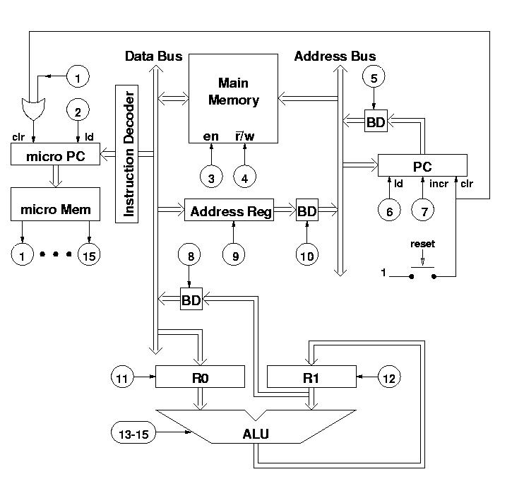
The diagram features a micro memory capable of storing up to 64 different addresses, each containing 15 bits, referred to as micro operations (MOPs). These MOPs govern all functions of the computer. Adjacent to the micro memory is the...
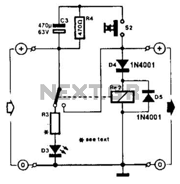
A charged capacitor C3 and a momentary pushbutton switch S2 are utilized to temporarily activate relay RE2. The battery being charged powers the relay to maintain its closed state. Additionally, S2 can energize the relay even if the battery...
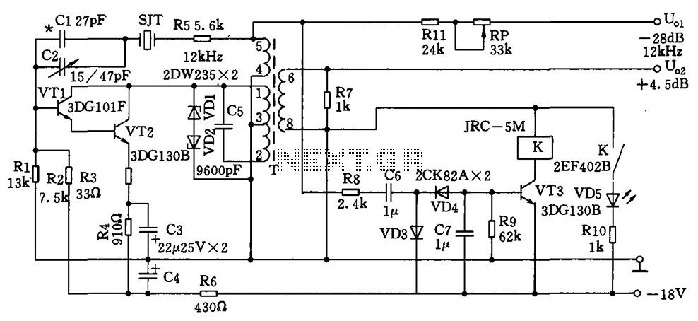
The circuit depicted is a 12 kHz intermediate frequency oscillator designed for an alarm system. It employs a variable feedback oscillation circuit where the oscillation frequency is primarily determined by a quartz crystal. Capacitors C1 and C2 are used...

The schematic for the board is illustrated below. The three primary components of the board include (1) the power input and voltage regulation, (2) the L297 input and outputs, and (3) the L298 stepper motor control circuit. The motor...
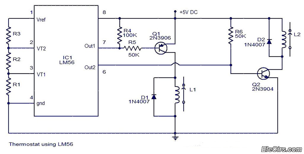
The LM56 Thermostat Project Circuit Diagram includes a schematic for the LM56 thermostat. The values of resistors R1, R2, and R3, which determine the required trip points VT1 and VT2, can be calculated using the following equations: VT1 =...
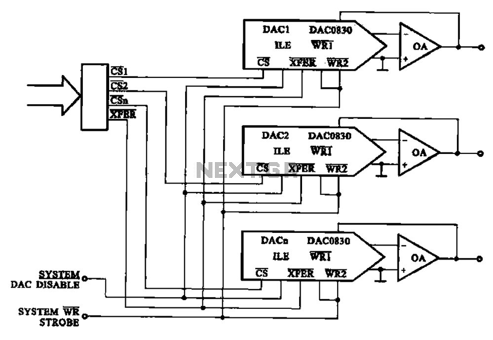
A multi-channel D/A converter circuit is presented, illustrating its fundamental structure. This circuit effectively converts encoded digital signals into multiplexed analog signal outputs. The multi-channel Digital-to-Analog (D/A) converter circuit is designed to facilitate the conversion of digital signals into corresponding...