
555 timer Clap switch circuit electronic project

This clap switch circuit utilizes a 555 timer IC configured in monostable mode to create a responsive lighting system activated by sound. The microphone acts as a sensor, picking up clap sounds, which are then amplified through a series of transistors (T1, T2, and T3) to ensure the signal is strong enough for processing. Diode D1 plays a crucial role in detecting the clap sound, converting the audio signal into a usable voltage signal that triggers T4.
Transistor T5 serves to further amplify the signal, ensuring that the 555 timer receives a sufficient input to activate. The 4017 decade counter receives pulses from the 555 timer output, allowing for sequential activation of connected loads, such as lamps. The use of transistor T6 allows for alternating control of the lamp, enabling it to switch on and off with each clap detected.
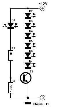
The circuit's power supply is ingeniously derived from the mains voltage, with diode D2 functioning as a rectifier to convert AC to DC. Resistor R16 and zener diode ZD1 work together to stabilize the voltage at 12 volts, ensuring consistent operation of the entire circuit. The choice of triac, such as the 8T44A or ST044, is critical, as it must handle the load current effectively, rated at up to 4 amps, making it suitable for driving various light sources. Overall, this clap switch circuit exemplifies an efficient design that merges audio detection with practical lighting control, demonstrating the versatility of the 555 timer IC in electronic projects.This 555timer clap switch circuit electronic project is designed using some common electronic parts. This 555 timer clap switch circuit electronic project operates from a distance of up to 10 meters from the microphone. Signal from microphone is amplified by transistors T1, T2 and T3. Diode D1 detects clap signals and the resulting positive volt age is applied to the base of the transistor T4. T5 transistor will amplify the output signal from the T4 transistor and will trigger the monostable multivibrator based on the 555 timer IC. The output signal from the 555 timer IC is used as a clock for a 4017 decade counter. For each successive clap T6 conducts and cuts off alternately, resulting and on of switching for the lamp.
Triac used for this project can be a 8T44A or ST044 and can drive load up to 4 amp rating. The 12 volt for powering this electronic circuit project is derived directly from the mains using rectifier diode D2 and some other components like R16 and ZD1 zener diode. 🔗 External reference
Related Circuits
Its state is constantly changing, and this change affects the flow of current and voltage, which is visible with the two LEDs. The speed of the LED flasher can be adjusted with potentiometer P1. As an astable multivibrator, the...

This entry is for the international 555 Contest. The 555 timer chip has been in use for many years and is highly versatile. The concept of this project addresses the need for notification of an event while away from...

This is a simple circuit for automatic switchover between battery and USB port. This circuit uses a more general step-up converter architecture. The circuit designed for automatic switchover between a battery and a USB power source employs a step-up...
A fast electronic fuse designed to operate on 230V AC with an adjustable trip current. When the current through the load exceeds a level determined by the user, the fuse will trip to protect the circuit. The electronic fuse functions...

The transistor characteristic curve tracer circuit depicted in Figure 555 illustrates the characteristics of a transistor. It utilizes two voltages: a step wave applied to the base (b) to generate different base currents (Ib), and a sawtooth waveform at...

The low-cost Mini-Circuits MAR-X series of chips provides a significant advantage for RF builders, featuring inherent 50-ohm input and output impedances essential for RF systems. An MAR-1-based receiver/scanner preamplifier is illustrated. Capacitors Ci and C2 are chip capacitors, with...