
Touch Switch with relay

Part List
R1=10M 1/4W 5% [See Text] R6=1K 1/4W 5% D2=3.9V 0.4W ZENER
R2-3=1M 1/4W 5% C1-2=470nF 63V MKT D3=LED RED
R4=33K 1/4W 5% C3=47nF 63V MKT Q1=BD679
R5=1.8K 1/2W 5% C4=22uF 25V IC1=4011
D1=1N4148 RL1=12V Relay
The circuit described is a simple touch-activated relay control system. The primary function is to toggle the state of relay RL1, which can control various loads or devices connected to its contacts. The activation mechanism relies on a small metal surface that, when touched, triggers the circuit.
The power supply for the entire circuit is +12V, which is suitable for energizing the relay RL1, rated for 12V operation. The heart of the control logic is the integrated circuit IC1, which is a quad 2-input NAND gate (CD4011), functioning here to process the signal from the touch sensor.
The voltage supply for IC1 is regulated to 3.9V using a zener diode (D2) in conjunction with resistor R5. This voltage regulation is crucial as it ensures that the logic levels are compatible with the operation of the IC. The combination of R5 and D2 forms a simple voltage divider and clamping circuit, which stabilizes the voltage supplied to the IC.
The touch-sensitive input is likely connected to the gate of transistor Q1 (BD679), which acts as a switch to control the relay. When the metal surface is touched, it creates a low-resistance path that allows current to flow, turning on the transistor. This, in turn, energizes the relay coil, closing the contacts of RL1.
LED D3 serves as an indicator for the state of the relay. When RL1 is energized, D3 lights up, providing a visual cue that the relay contacts are closed. This is useful for confirming the operation of the circuit without needing additional testing equipment.
Resistors R1, R2, R3, R4, and R6 are used to set the biasing and gain conditions for the circuit components, ensuring proper operation. Capacitors C1, C2, C3, and C4 are included for filtering and stability, helping to reduce noise and provide a stable operation.
In summary, this circuit offers a straightforward solution for touch-activated control of a relay, with visual feedback provided by an LED, and is designed with common electronic components that ensure reliability and ease of assembly. Adjustments to resistor values, particularly R1, may be necessary to fine-tune sensitivity and performance based on specific application requirements.A simple circuit with which we have the possibility opening and closing the RL1 contacts. He becomes touching a small metal surface. Clue of situation that is found RL1, is become by the Led D3. The supply of circuit is +12V, the IC1 is supplied with 3.9V fall of voltage that is ensured by combination R5 and zener D2. For more good restoration perhaps it should adaptation of R1 value. Part List R1=10M 1/4W 5% [See Text] R6=1K 1/4W 5% D2=3.9V 0.4W ZENER R2-3=1M 1/4W 5% C1-2=470nF 63V MKT D3=LED RED R4=33K 1/4W 5% C3=47nF 63V MKT Q1=BD679 R5=1.8K 1/2W 5% C4=22uF 25V IC1=4011 D1=1N4148 RL1=12V Relay 🔗 External reference
Related Circuits
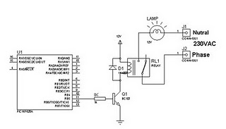
A relay can be controlled using a PIC microcontroller. The circuit illustrates how to control a single relay with the PIC 16F628. When the RB5 port of the PIC is set to high, the relay will activate. This circuit...

If the total circuit resistance can be significantly reduced to less than 0.1 Ohm and a load of 0.4 Ohm or less is connected, over 1 kilowatt of free electrical energy can be obtained. There are two discrete voltage...
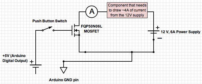
If the ground of the Arduino is disconnected from the negative terminal of the power supply, current flows through the MOSFET, even when the switch is not closed. In an electronic circuit involving an Arduino and a MOSFET, maintaining a...

Utilize the call sheet to touch the electrical threshold M, which causes the E lamp to light up. When the same interval subparagraph is triggered, the lights will automatically turn off. A voltage regulator rectifier circuit is formed using...
This circuit is similar to the previous one but incorporates a photoresistor to trigger the flip-flop instead of a push button. A bias resistor is placed in series with the photoresistor to ensure that adequate voltage is present at...
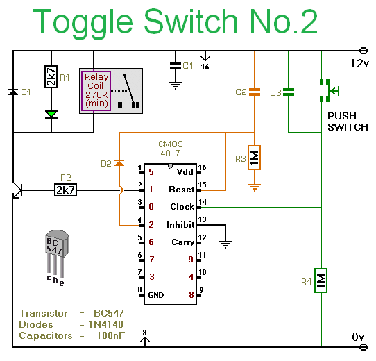
This circuit utilizes a CMOS 4017 decade counter, which begins counting from zero and advances by one each time pin 14 is activated. Upon reaching nine, the count resets to zero and starts over. As the count progresses, each...