
Logic adjustable Glow-Plug drive

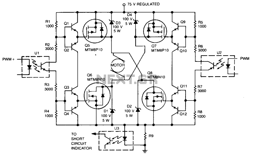
The circuit in question is a modified Pulse Width Modulation (PWM) motor driver designed specifically for controlling a glow plug ignition system. The choice of a glow plug over a spark ignition system is primarily due to the inherent safety and compatibility of the lower voltage requirements with sensitive electronic components, as opposed to the high voltage associated with spark ignition systems, which can exceed 30,000 volts.
The PWM motor driver circuit typically consists of a microcontroller or a dedicated PWM controller that generates a square wave signal. This signal is used to control a power transistor or MOSFET, which acts as a switch to regulate the power delivered to the glow plug. The duty cycle of the PWM signal determines the average power delivered, thereby controlling the temperature of the glow plug to ensure optimal ignition conditions.
Key components of the circuit include:
1. **Microcontroller or PWM IC**: This component generates the PWM signal and can be programmed to adjust the duty cycle based on feedback from temperature sensors or other monitoring devices.
2. **Power Transistor/MOSFET**: This acts as the switch that controls the current flowing through the glow plug. It must be rated for the appropriate voltage and current levels to handle the load without overheating.
3. **Glow Plug**: A resistive heating element that ignites the fuel-air mixture in the combustion chamber. It requires a specific voltage and current rating, typically around 12V to 24V.
4. **Flyback Diode**: Used to protect the circuit from voltage spikes caused by the inductive load of the glow plug when it is switched off.
5. **Power Supply**: A stable DC power source that provides the necessary voltage and current for the operation of the glow plug and the control circuitry.
The circuit may also incorporate additional features such as:
- **Feedback Mechanisms**: To monitor the temperature of the glow plug and adjust the PWM signal accordingly to maintain optimal performance.
- **Safety Features**: Such as overcurrent protection and thermal shutdown to prevent damage to the components in case of a malfunction.
This design, while not claimed as original, effectively utilizes existing PWM motor driver principles to create a reliable and efficient glow plug ignition system, minimizing the risks associated with high-voltage spark ignition systems.All of my turbine starts before the research on the ECU involved a very successful spark ignition. I thought (only briefly) of trying to add spark ignition to the ECU, but the mixture of delicate logic circuitry and perhaps 30,000V simply don`t mix. My past experience with the hall sensor ignition for the radial engine bears this out in painful detail. So I decided to go with a glow-plug driver. I claim no great originality to this circuit... it is a modified PWM motor driver which happens to work 🔗 External reference
Related Circuits

NEC's UPB1008K is a Silicon RFIC specifically designed for handheld low-power, low-cost GPS receivers. The integrated circuit combines a low-noise amplifier (LNA) followed by a double-conversion RF/IF downconverter block and a phase-locked loop (PLL) frequency synthesizer on a single...
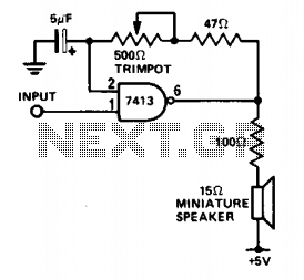
This circuit is useful for monitoring slow logic pulses as a keying monitor or digital clock alarm. The Schmitt trigger is connected as an oscillator. The trimpot controls the pitch of the output. When the input goes high, the...
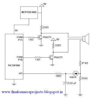
A horn driver project developed by Microchip Technology is illustrated in this circuit diagram. This horn driver project utilizes the PIC16F886 microcontroller from Microchip. The circuit diagram for the PIC microcontroller horn driver is straightforward and requires minimal external...
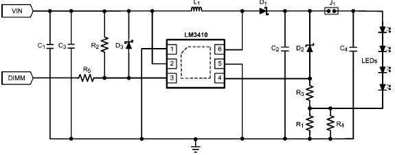
The LM3410 constant current LED driver is a monolithic integrated circuit that enables the design of high-efficiency, low-cost lighting solutions using a minimal number of electronic components. It employs current-mode control and internal compensation to ensure optimal performance across...
To simplify the driver circuit, a multiplexer circuit can be utilized as a solution. With this multiplexed BCD decoder, only one BCD is required. A multiplexer (MUX) is an essential component in digital circuits, allowing multiple input signals to be...
Digital integrated circuits (ICs) and opto-isolators drive this TMOS servo amplifier, resulting in fewer analog circuits and reduced drift. The fast and consistent turn-on and turn-off characteristics enable accurate analog output results directly from the digital signal without requiring...