
logic based digital queuing

The 74192 up/down counter is a synchronous binary counter that can count in both directions, providing flexibility in counting applications. It operates on a clock signal and can be controlled using up and down control pins. The counter can be reset to zero or preset to a specific value, depending on the configuration of the control inputs.
In this design, the RS latch serves as a memory element that holds the current state of the counter output. The RS latch is triggered by the output of the 74192, ensuring that the displayed counter number is stable and does not fluctuate with the clock signal. This aspect is crucial for applications where a reliable indication of the count is necessary.
The circuit may also include additional components such as resistors and capacitors for debouncing the control signals and stabilizing the power supply. Proper power management and decoupling techniques should be employed to ensure the reliable operation of the IC, especially in environments with electrical noise.
Overall, this simplified design effectively demonstrates the functionality of the 74192 up/down counter and the integration of an RS latch for output indication, making it suitable for various counting applications in digital electronics.This is a simplified design using a up/down counter IC, 74192. It is a versatile logic IC that has a separate pins for up and down count. Also, an RS latch is used for the indicator of the counter number. 🔗 External reference
Related Circuits
U1 is the 3817 integrated circuit, capable of directly driving the display. It can show time in either 12-hour or 24-hour format, schedule alarm sounds, and automatically turn on the radio at specified times. The display utilizes the FND500...
This circuit generates a readout for a digital tachometer. IC9 functions as a 3-digit LED display driver, counter, and latch. IC8 operates the common cathode LEDs, which are activated by transistors Q1, Q2, and Q3. Refer to page 268,...
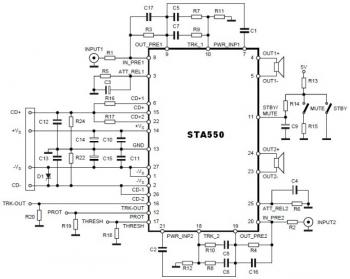
This is a stereo amplifier circuit diagram. The amplifier will produce stereo output channels with a power audio output that can reach up to 70W for each channel. The amplifier is built using the STA550 chip from STMicroelectronics. It...
The figure illustrates the schematic for a versatile logic probe. The zener diode clamps the input signal slightly above the TTL inverter's 2.2-V trigger voltage. Zener diode D1 can be omitted if the probe is intended solely for use...
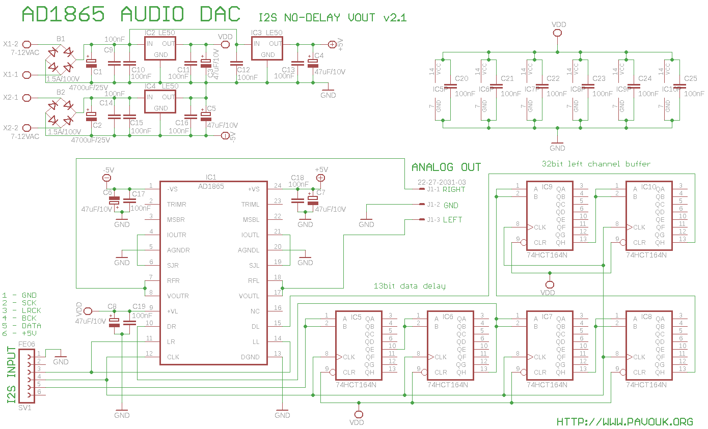
The AD1865 circuit is regarded as one of the best 18-bit stereo audio DACs available. Previous DAC designs encountered issues with weak current output, leading to the decision to utilize the integrated current-to-voltage (I/V) converter instead of an external...
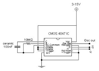
This circuit generates a digital square wave that can be displayed directly or utilized to drive additional circuits. It employs the CMOS 4047 Low-Power Monostable/Astable Multivibrator, as referenced in Tom Duncan's "Adventures with Digital Electronics" book, to control a...