
logic circuit diagram

The circuit design employs the LM324 operational amplifier, which consists of four independent, high-gain, frequency-compensated operational amplifiers. The primary function of the circuit is to compare two voltage levels. The first voltage level, U1, is set by the resistor R1 in conjunction with the input voltage, while the second level, U2, is established by resistor R2. The output from operational amplifier A1 will transition from low to high when U1 surpasses U2, effectively creating a comparator that can be used in various applications such as level detection or signal processing.
The truth table referenced indicates that the output Y is a function of the binary input X, where Y = 2X + 5. This implies that for every binary input, the output is derived by shifting the input left by one bit (multiplying by 2) and adding 5. This operation can be implemented using combinational logic circuits, where binary addition and shifting operations are performed using logic gates.
The control mechanism for steering logic levels is crucial for interfacing different voltage domains, especially when working with devices that operate at varying logic levels. A logic level switch can be designed using transistors or dedicated voltage-level translation ICs, facilitating the safe and effective communication between components.
In summary, this circuit integrates analog and digital components to achieve a specified functionality, utilizing operational amplifiers for voltage comparison and logic circuits for binary manipulation. The design emphasizes modularity and adaptability, allowing for further enhancements and integration into larger systems.The two drawings using the LM324 op amp to form a lower voltage comparator, resistor R1, R1 component partial pressure circuit, the op amp A1 is set at a level U1; resistor R2, R2 voltage divider formed for the op amp Comparison of A2 to set the level U2. Also added to the input voltage U1 A1`s positive input and negative input of A2 between, when U1, the output of op amp A1 high; when Ui truth table, find the. X 2-bit binary number is to design a circuit so that the output Y = 2X 5 (Y is binary), drawing. 2 How to control the steering with steering logic level, find the schematics and code! level switch 36, through the logic encoding, decoding, and digital display which switches out the problem. more the same subject matter: the schematic logic level to answer a total of one other Vision of the operation to clean heated ceramic circuit clean workshop, advanced production equipment, perfect testing equipment, excellent team.
Texas Instruments Voltage-Level Translation The of logic chips, logic devices and to provide professional solutions, triggers, Little Logic, reverse, etc. resettable current protection industry leader in the field of circuit protection Home ReCenter Sequential Logic Circuit Analysis Problem - Question 5.
1 of the logic circuit you are a normal registered user can only the contents of some of the res. Union, the user can the full content of the re. (Using points, you can res) Add tag Add to Favorites I would like to add a correction with the course Introduction 0 0 res under this reconcern is also concerned about the timing logic circuit of exercises - Question 5. 1 of the logic circuit media material 5 user rethere are 0 all the the following words into User Re, do not represent this site (please comply with state laws and regulations and ethical online) verification code, please refresh the anonymous tips up and then log on to, before publication, please refer to the following requirements: Respect for the online ethics and compliance, "the NPC Standing Committee`s decision on safeguarding Internet security" and other relevant laws and regulations of the PRC Your network at the national excellent course res for reand message board of a published work, the National Excellent Courses Res Network website have the right to reprint or quote Report E-mail: jingpinke@pub.
hep. cn From: Original Subject Category: Reof Electric Information: Zou Tao Ping ReType: Media Clip Media Type: Animation upload time :. ReLanguage: Chinese resize: 29 KB Res Page: Res Length: Hits: 5 Related tags: $ {Jingpinke_re_courseID} Sequential Logic Circuit Analysis Problem - Question 5.
1 of logic circuit 01009 01009006 Electrical and Information Engineering University 0swfrawff808081-1e72b09d-011e-72b09f2c-1787oid: ff808081-1e72b09d-011e-72b09f2c-1784union related courses Xuewu De Circuit Circuit Circuit Zhang Fengshan Tan Zhenyu Wu Chengdong circuit circuit materials related to user error correction PROCEEDINGS 194 0To avoid detours as possible, we must actively and steadily promote the reform of education, so step by step. [more] 🔗 External reference
Related Circuits
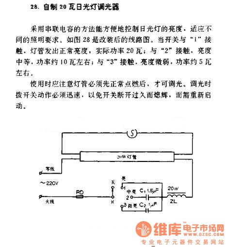
A homemade 20W fluorescent lamp dimmer utilizes a series capacitor connection to effectively control the brightness of fluorescent lamps, allowing for adaptability to various lighting requirements. In the modified circuit diagram (Figure 28), when the switch is set to...

The LT6552 is a video difference amplifier optimized for low voltage single supply operation. The LT6552 features a 75MHz 3dB bandwidth, a 600V/µs slew rate, and ±70mA output current, making it ideal for driving cables directly. This circuit maps...
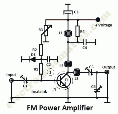
This is a 1 watt FM amplifier with a robust design that can be used to amplify an RF signal in the 88 to 108 MHz band. It is highly sensitive when utilizing quality RF power amplifier transistors, trimmers,...
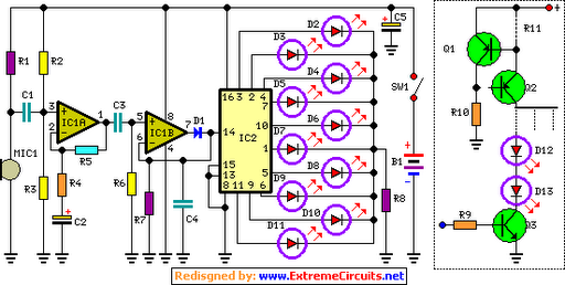
The basic circuit illuminates up to ten LEDs in sequence, following the rhythm of music or speech picked up by a small microphone. The expanded version can drive up to ten strips, each formed by up to five LEDs,...
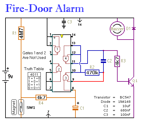
This circuit provides an alert when a door that should remain closed is left open. It is designed to be attached to a fire door, allowing normal passage. If the door remains open for more than 30 seconds, a...
This electronic organ circuit is straightforward to construct and primarily consists of an emitter-coupled oscillator formed by transistors T2 and T3. A square wave voltage can be obtained from the collector of T3 (X2), which imparts a clarinet-like quality...