
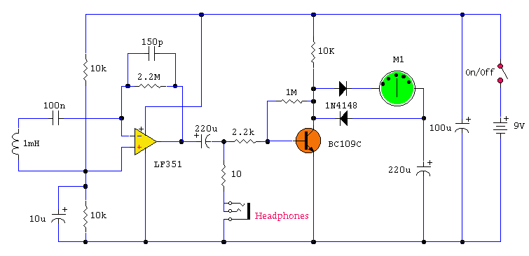
Logic Probe

The described circuit serves as a simple yet effective voltage and logic level indicator, utilizing two test lamps to provide visual feedback on the status of a connected logic device. The circuit operates based on the principle of voltage detection, where the state of the circuit influences which lamp illuminates.
The circuit comprises two test lamps, typically LED indicators, connected in parallel with appropriate current-limiting resistors. The first lamp, designated as the low-voltage indicator, is configured to illuminate when the voltage is at or near zero, indicating a grounded condition. The second lamp, the high-voltage indicator, is designed to activate when a voltage between 3 to 6 V is detected, signaling the presence of a valid logic high state.
Resistor selection is critical for determining the activation thresholds for the lamps. By choosing resistors with specific values, one can fine-tune the circuit to respond to various voltage levels, ensuring that the indicators operate within the safe limits of the components used. This flexibility allows for customization based on different logic families or supply voltages.
For practical implementation, the circuit can be powered by the same supply voltage as the logic device being tested, simplifying the setup. The test probe can be connected directly to the output of the logic device, providing immediate visual feedback on its operational status. This makes the circuit an invaluable tool for troubleshooting and verifying the functionality of electronic circuits in various applications, including digital logic testing, power supply verification, and ground checking.
The overall design is straightforward, requiring minimal components, which enhances its reliability and ease of use. The circuit can be housed in a compact enclosure, with the test lamps visible from the outside, allowing for quick assessments without the need for additional measuring equipment. By connecting this circuit to a logic device that"s under power, you can get an indication as to its status. If the circuit is open, neither of the test lamps will light. If the circuit is grounded, the low (or zero) lamp will light. If 3 to 6 V are present, the high-voltage lamp will light. Other than its application in logic testing, the probe is also convenient for checking supply voltages and grounds. You can select resistors to turn the lamps on at any desired threshold voltage within the component limits.
Related Circuits
This tester is designed to locate stray electromagnetic (EM) fields. It can easily detect both audio and RF signals up to frequencies of approximately 100 kHz. However, it should be noted that this circuit is not a metal detector,...
The design of the digital logic probe centers around a pair of complementary bipolar transistors, which, in this application, are used as electronic switches. The digital logic probe is a diagnostic tool utilized for testing and analyzing digital circuits. The...
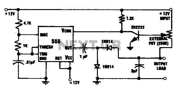
This circuit integrates a 555 timer with a 2N2222 transistor and an external potentiometer. The potentiometer adjusts the output voltage to the desired level. The 2N2222 transistor regulates the output voltage by varying the control voltage of the 555...
A logic pen, also known as a logic detection probe, is a commonly used tool for detecting the logic state at various points within digital circuits. The logic states in digital circuits are typically categorized into three types: a...
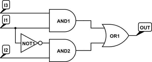
There are integrated circuits that contain AND, OR, and NOT gates. The inquiry revolves around the existence of a single chip that encompasses all the required logic gates. If such a chip does not exist, specific alternatives should be...
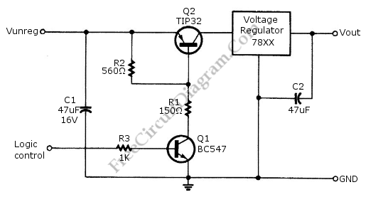
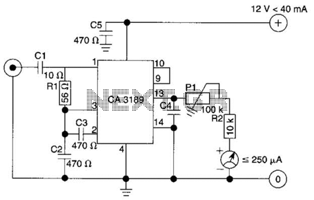
Logic power control of an analog regulator can be useful in applications where a digital circuit or controller needs to manage a power source, such as in EEPROM. In electronic systems, managing power effectively is crucial for the performance and...