
Logic Probe for Tri-state Logics

The Logic Probe circuit for tri-state logic is designed to detect and indicate the state of digital signals in a circuit that can exist in three different states: high, low, and high-impedance (or tri-state). This is particularly useful for troubleshooting digital circuits where multiple devices may share a common bus.
The basic components of a Logic Probe circuit typically include a microcontroller or logic gates, resistors, diodes, and LEDs for visual indication. The circuit operates by applying the input signal to a comparator, which determines the voltage level of the signal. If the signal is high (logic 1), the corresponding LED will illuminate, indicating a high state. Conversely, if the signal is low (logic 0), another LED will light up to indicate a low state. In the case of a high-impedance state, the circuit will not activate either LED, allowing the user to identify the tri-state condition.
Power supply considerations must also be addressed, as the circuit usually requires a stable voltage source, typically between 5V to 15V, depending on the logic levels being monitored. The design can be compact, often implemented on a small printed circuit board (PCB) to facilitate portability and ease of use.
Additionally, protective components such as current-limiting resistors and clamping diodes may be included to prevent damage to the circuit from over-voltage conditions. The Logic Probe can be an invaluable tool in debugging and validating the functionality of digital systems, providing clear visual feedback on the state of the signals being monitored.This is a simple circuit of Logic Probe for Tri-state Logics. This circuit can be built only in a few hours. Besides that, this circuit has some other. 🔗 External reference
Related Circuits
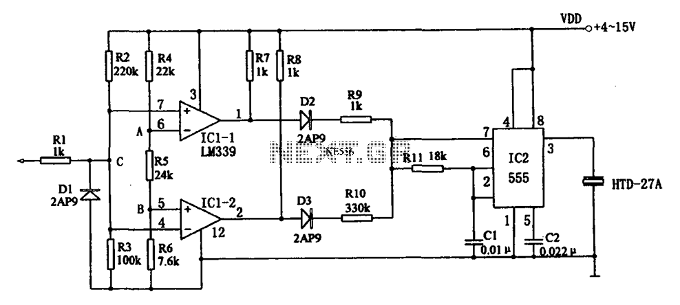
The acoustic logic level probe circuit consists of a voltage comparator, multivibrator, piezoelectric ceramics (HTD), and other components. The configuration of the audio circuit determines the frequency of the sound level to assess the logic levels of TTL or...
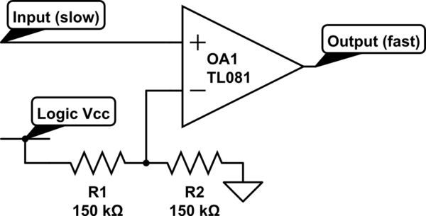
Invert a signal to drive FETs with rapid rise and fall times. It was suggested to use an inverter (not a chip) instead of logic chips, which are designed to be either fully ON or OFF. The individual has...
When testing circuits with a logic probe, it is sometimes difficult to watch the LEDs on the probe to determine the logic state. With this probe, the logic states are audible. This probe is designed for TTL circuits only...

The circuit presented utilizes NAND logic gates from the Hitachi HD series, specifically the HD74LS00, which is a quad NAND integrated circuit. A special technique has been implemented to achieve three-state operation using a single IC. Gate N1 is...
The probe described here was designed to be used over the range of several tens of Hz to a couple MHz with currents from a few tens of milliamps to about 10 amps peak-to-peak. Formulae are given which will...
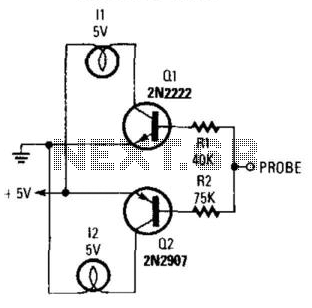
By connecting this circuit to a powered logic device, an indication of its status can be obtained. If the circuit is open, neither of the test lamps will illuminate. If the circuit is grounded, the low (or zero) lamp...