
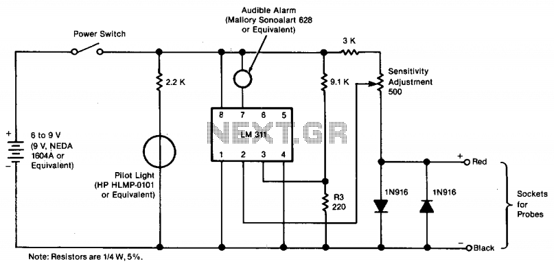
Audible Logic Probe with LM339

The audible logic probe operates based on the voltage levels present in TTL (Transistor-Transistor Logic) circuits. The primary components of the probe include a voltage comparator, a tone generator, and an audio output device, typically a small speaker or piezo buzzer.
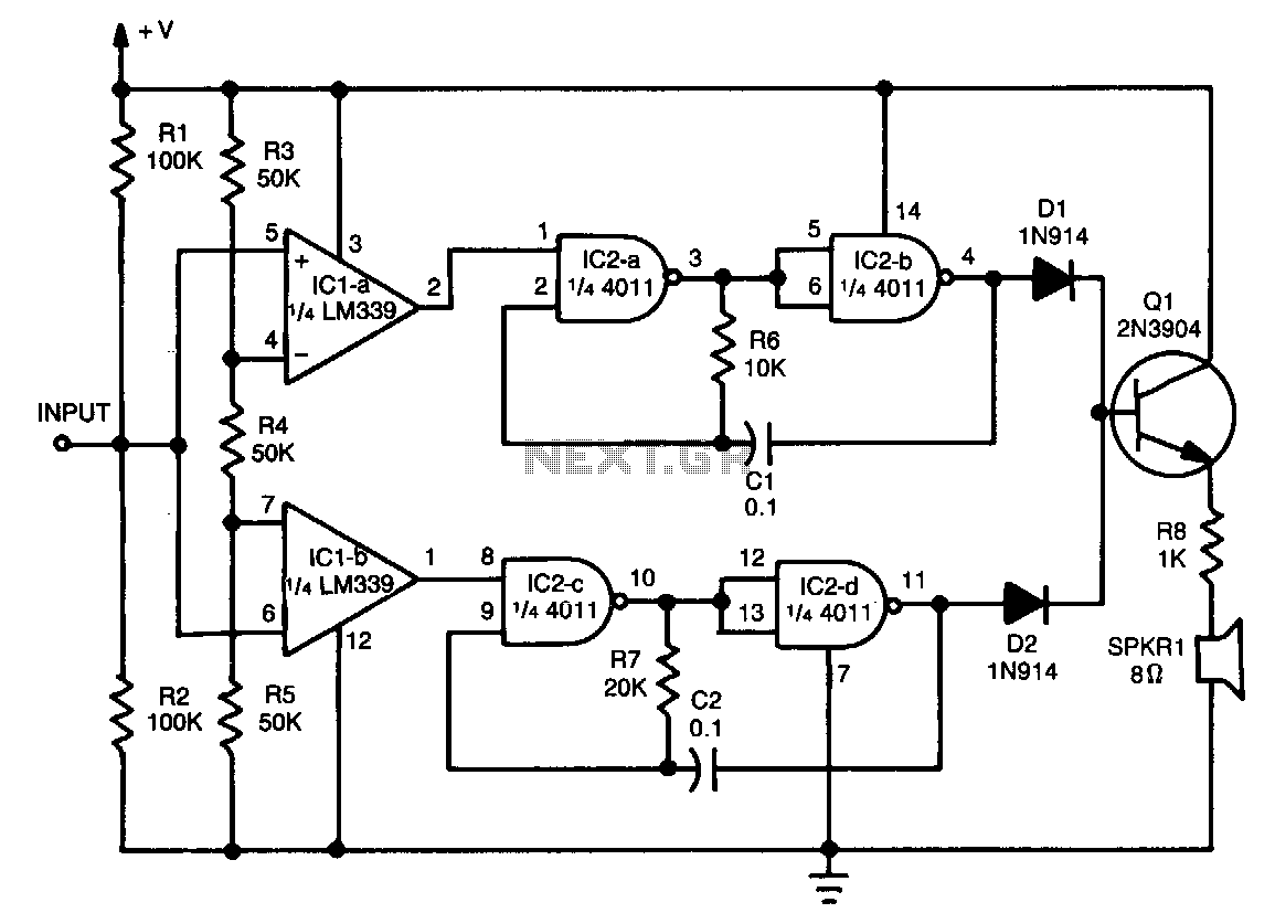
The voltage comparator is configured to compare the input voltage from the circuit under test against two reference voltages: 2 volts and 0.8 volts. When the probe tip is connected to a point in the circuit, the input voltage is fed into the comparator. If the voltage exceeds 2 volts, the comparator outputs a signal that activates the tone generator to produce a high-frequency tone, indicating a logic high state. Conversely, if the voltage falls below 0.8 volts, the comparator triggers the tone generator to produce a low-frequency tone, indicating a logic low state.
For proper operation, the probe is powered by a 5-volt source, which is typically the same voltage used in TTL circuits. The ground clip must be connected to the circuit's ground to ensure accurate voltage readings. The probe's design can be adapted for CMOS (Complementary Metal-Oxide-Semiconductor) circuits by adjusting the reference voltage levels to accommodate the different voltage ranges used in those applications.
In summary, the audible logic probe is a valuable tool for quickly assessing the logic state of various points in a TTL circuit, providing immediate auditory feedback that can enhance the efficiency of circuit testing and troubleshooting.When testing circuits with a logic probe, it is sometimes difficult to watch the LEDS on the probe to determine the logic state. With this probe the logic states are audible. This probe is designed for TTL circuits only but could be modified for CMOS. The way it works is as follows. The 5 volt power source will be the circuit under test. Clip the ground input of the probe to the ground of the circuit being tested. The other input lead is used to probe the different chips of the circuit being tested. Any input greater then 2 volts will be high and output a high tone through the speaker. Any input less then .8 volts will be low and produce a low tone through the speaker. 🔗 External reference
Related Circuits
The tester provides an audible indication, eliminating the need for the user to directly observe a meter reading. Additionally, the current and voltage output of the tester are strictly limited, with a maximum of 0.6 volts DC and 3...
A two-transistor Darlington connection offers a very high input impedance, ensuring that it does not load the logic circuit being monitored. This configuration drives an LED that illuminates when a logic high (1) is present at the input. The two-transistor...

This circuit utilizes two quad voltage comparators, specifically the IC LM339, to illuminate a series of eight LEDs that indicate volume levels. Each of the eight comparators is biased at increasing voltages set by a voltage divider, allowing the...
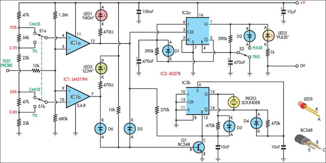
This logic probe can be selected to operate on TTL or CMOS logic levels, depending on switch S1. A string of resistors associated with switch S1 sets the threshold levels for a window comparator comprising IC1a and IC1b. Depending...
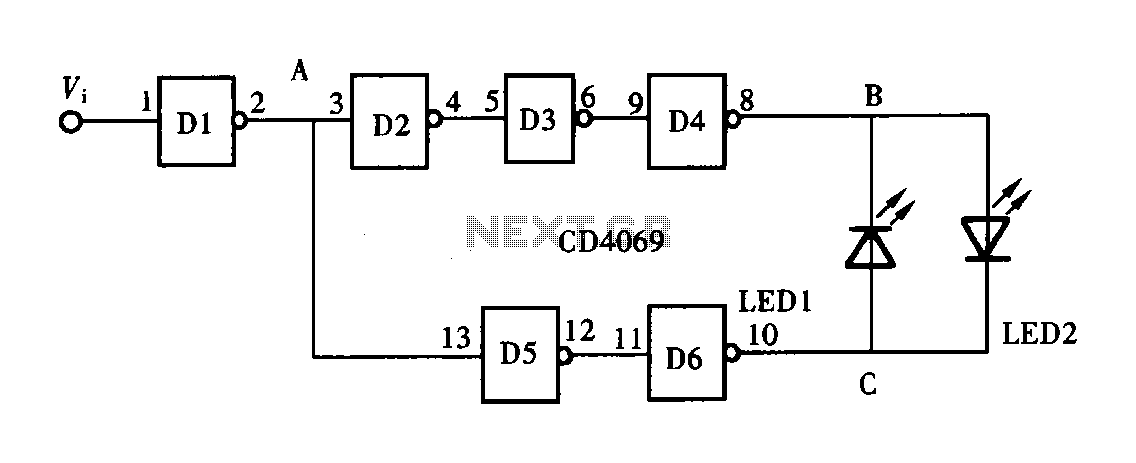
A logic pen, also known as a logic detection probe, is a commonly used tool for detecting the logic state at various points within digital circuits. The logic states in digital circuits are typically categorized into three types: a...
This tester provides an audible indication of the logic level of the signal presented to its input. A logic high is indicated by a high tone, a logic low is indicated by a low tone, and oscillation is indicated...