
Long range FM transmitter

The long-range FM transmitter operates by modulating a carrier frequency with an audio signal, allowing for the transmission of sound over considerable distances. To enhance the transmission range, the circuit typically includes several key components, such as an oscillator, a modulator, and an antenna.
The oscillator generates a stable frequency, which serves as the carrier wave. This can be achieved using a Colpitts or Hartley oscillator configuration, known for their reliability in producing sine waves. The frequency is usually adjustable to avoid interference with other stations.
The modulator stage combines the audio input with the carrier wave. This is often accomplished using a transistor configured as a mixer, where the audio signal is superimposed onto the carrier frequency, resulting in frequency modulation. The choice of transistor is crucial, as it must handle the desired frequency range and provide sufficient linearity to ensure high-quality audio transmission.
To amplify the output signal, a power amplifier stage can be added, which is often omitted in basic designs. This stage increases the output power to drive the antenna more effectively, thus extending the transmission range. Common configurations include class A or class C amplifiers, with the latter being more efficient for RF applications.
The antenna design also plays a critical role in the performance of the transmitter. A dipole or monopole antenna can be used, depending on the desired range and frequency. The antenna must be tuned to the transmitter's frequency to maximize radiation efficiency.
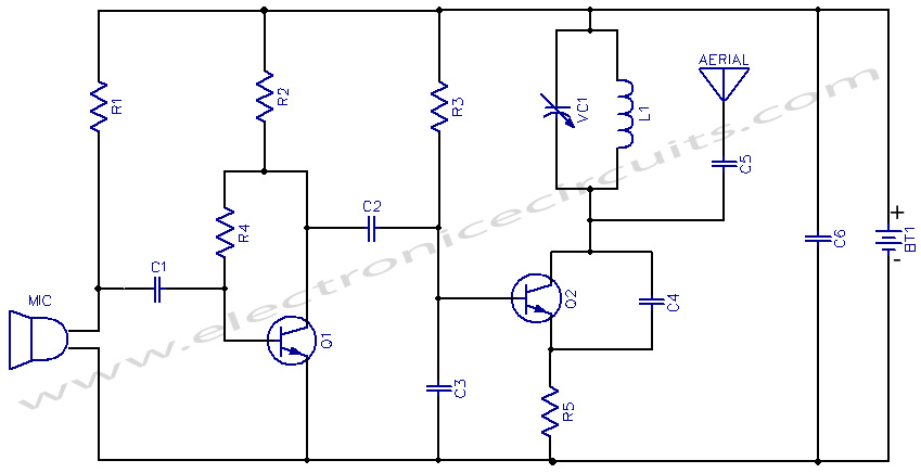
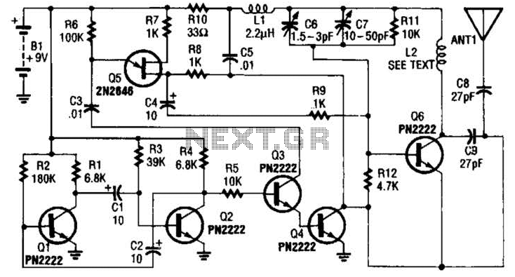
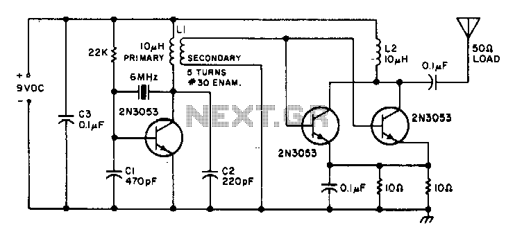
Overall, while many basic FM transmitter circuits may lack amplification stages, incorporating these additional components significantly enhances the transmission range and audio quality, making it suitable for various applications, such as broadcasting or personal use.Long range FM transmitter. The power output of most of these circuits are very low because no power amplifier stages were incorporated. The transmitter circuit described here has an. 🔗 External reference
Related Circuits
MC44BS373CA: PLL Tuned UHF and VHF Audio Video High Integration Modulator MC44BS373CA The MC44BS373CA Audio and Video Modulator is designed for use in VCRs, set-top boxes, and similar devices. Manufactured by Freescale Semiconductor, Inc. The MC44BS373CA is a highly integrated...
This project provides the schematic and the parts list needed to construct a 3V FM transmitter. This FM transmitter is one of the simplest and most basic transmitters to build, yet it offers a useful transmitting range. It is...
The transmitter utilizes a 6BW6 vacuum tube to achieve an output power of approximately 5 watts. The circuit includes a component CI that is calibrated to produce the cleanest continuous wave (CW) note. The tuning capacitors C8 and C9...
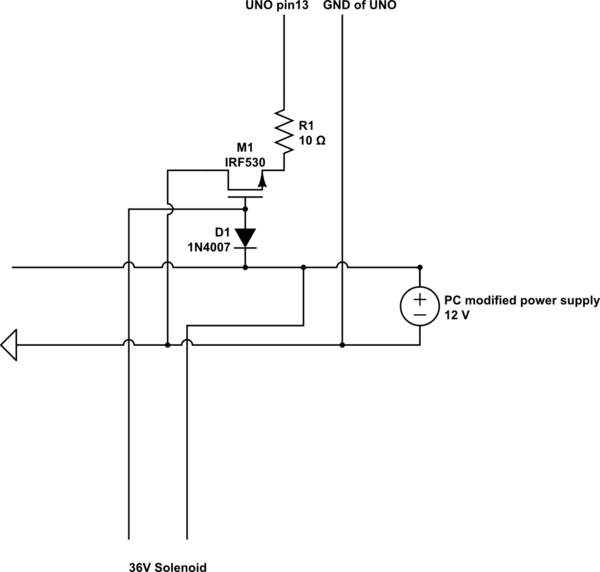
A 9 V DC battery initially powered the solenoid valve effectively. However, the solenoid did not generate sufficient force due to inadequate DC power. A modification was made to use a computer power supply as the power source. Providing...
This is a small transmitter designed to fit inside a plastic Easter egg. It delivers approximately 1 W of measured RF output into a 50-ohm dummy load and does not generate any heating issues within the circuit. The crystal...
The wide-range current pump for the precision phase-locked loop (PLL) circuit is a semi-precision circuit that provides an output current proportional to -V1, with a variation of approximately 10 to 15%, across a three-decade range. The 22 MΩ resistors...