
Vacuum Tube 80-40M Transmitter Circuit

The transmitter circuit is designed around the 6BW6 vacuum tube, which is known for its efficiency and reliability in RF applications. The output stage, powered by the 6BW6, is capable of delivering a stable output of around 5 watts, making it suitable for low-power transmission applications. The component CI, which is likely a variable capacitor or an inductor, plays a crucial role in tuning the circuit to achieve the clearest possible CW signal.
The tuning capacitors C8 and C9 are critical for frequency selection and stability. The use of a dual-365 pF capacitor in parallel with a single 365 pF capacitor allows for fine-tuning and provides a greater range of capacitance, which is essential for achieving precise frequency adjustments. The inductor LI, constructed from 35 turns of #24 enamelled wire on a 1-inch plastic tube, forms a resonant circuit with the tuning capacitors, enabling effective filtering and signal generation at the desired operating frequency.
The choice of FT-243 crystals for 3.5 MHz or 7 MHz operation provides a reliable frequency reference for the transmitter. However, it is imperative to adhere to the design specifications, as the circuit is not intended for frequency multiplication. Attempting to use a 3.5 MHz crystal to generate a 7 MHz output could lead to undesirable performance and potentially damage the circuit components. Proper selection and installation of the crystals are essential for optimal operation and signal integrity. Using a 6BW6 vacuum tube, the above transmitter delivers about 5 W output. CI is adjusted for cleanest CW note. C8 and C9 are 365 pF and dual-365 pF (paralleled) tuning capacitors. LI is 35 turns of #24 enamelled wire on a 1 plastic tube. FT-243 crystals for 3.5 or 7 MHz are used. Do not use this circuit to produce a 7-MHz output from a 3.5-MHz crystalit is not intended to double over crystal frequencies.
Related Circuits
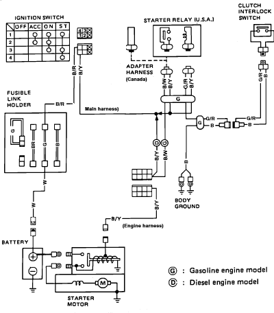
Nissan Sentra 1.6 Liter Manual Transmission Starter Circuit Wiring Diagram. The Nissan Sentra 1.6 Liter manual transmission starter circuit wiring diagram provides a visual representation of the electrical connections involved in the starting system of the vehicle. This diagram is...

Below 10 MHz, the development of engineering models is relatively straightforward and not significantly influenced by printed circuit board layout. In the VHF range, parasitic circuit elements and unwanted coupling can severely impact efforts to achieve cost-effective performance without...
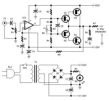
Proper grounding is essential for eliminating hum and ground loops. Connect the ground terminals of J1, P1, C2, C3, and C4 to the same point. Connect C6 to the output ground. An audio amplifier is an electronic device that...
This circuit enables the use of an inexpensive loudspeaker as a microphone. Sound waves that reach the speaker cone create fluctuations in the voice coil. The movement of the voice coil within the speaker's magnetic field generates a small...
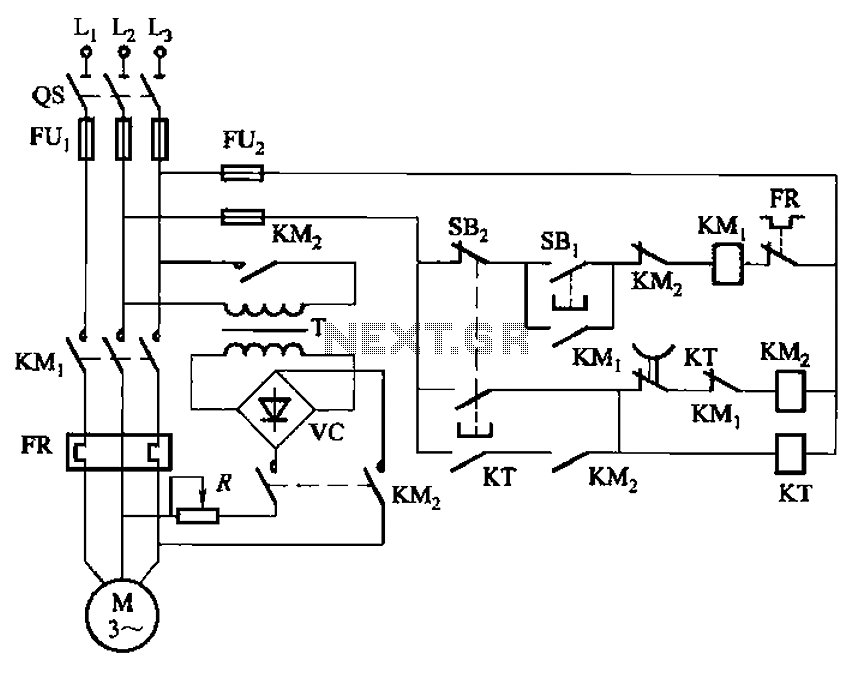
The circuit depicted in Figure 3-135 employs a time relay (KT) to determine the braking time. The circuit utilizes a time relay, which is a crucial component for controlling the duration of the braking process. The time relay KT is...
Figure 4-13 illustrates a modified version of a standard attenuated tone control from the pitch selector. It features two amplification stages of amplifiers 10 and Icl utilized as line amplifiers. Capacitor C2 is employed to compensate for tone attenuation...