
Long range FM transmitter electronic project

This FM transmitter circuit is designed to operate efficiently within the specified frequency range, making it suitable for various applications such as hobbyist projects and educational demonstrations. The use of BC547 transistors in the initial stages allows for effective signal amplification and modulation due to their favorable characteristics in low-frequency applications. The Hartley oscillator configuration is particularly advantageous for generating stable RF signals, as it utilizes the inductance of the coil (L1) and the variable capacitance of the trimmer capacitor to establish the desired frequency.
In this circuit, the modulation process is critical, as it determines the quality and clarity of the transmitted audio signal. By adjusting the voltage at the base of the second transistor (T2), the junction capacitance changes, which in turn affects the resonant frequency of the tank circuit. This allows for dynamic tuning of the transmitter output, enabling it to adapt to different audio sources or transmission conditions.
The final amplification stage, built around the RF transistor T3, is responsible for increasing the power of the RF signal to a level suitable for transmission over longer distances. The careful selection of the 10pF ceramic capacitor alongside the red trimmer capacitor ensures that the circuit can be finely tuned, providing flexibility in operating frequency and improving overall transmission quality.
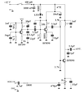
Overall, this FM transmitter circuit exemplifies a well-structured approach to RF signal generation and modulation, emphasizing simplicity and effectiveness in design while adhering to the operational constraints of the commercial FM band.This FM transmitter electronic project is a very simple and powerful transmitter circuit with a range up to 1 kilometer in the open air. This FM transmitter electronic project uses an RF transistor in its output stage and two BC547`s for the first two stages.
Output from the collector is fed into the base of the second transistor where it modulate s the resonant frequency of the tank circuit (L1 coil and the red trimcap) by varying the junction capacitance of the transistor. Junction capacitance is a function of the potential difference applied to the base of the transistor T2.
The tank circuit is connected in a Hartley oscillator circuit. The final stage built around T3 amplifies the output RF signal. The 10pF ceramic capacitor in parallel with the red trim cap will enable you to tune the transmission in the 98 MHz to 105 MHz range of the commercial FM band. 🔗 External reference
Related Circuits
A low-power two-stage FET transmitter designed for the 80-meter amateur band utilizes a Pierce crystal oscillator that does not require an output resonant circuit. A DC milliammeter can be connected across a 150-ohm resistor in the gate circuit of...
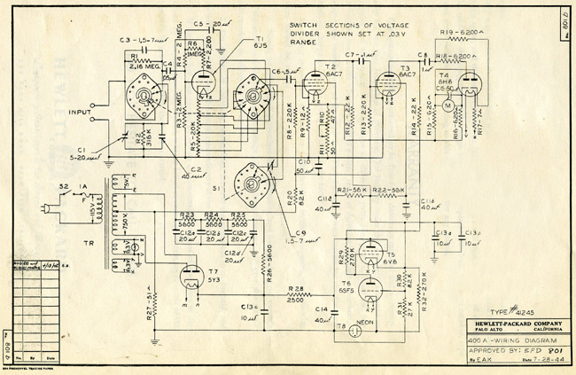
The HP Model 400A Vacuum Tube Voltmeter is highly versatile due to its extensive frequency and voltage ranges. It can directly measure AC voltages as low as 0.005 volts and as high as 300 volts across a frequency range...
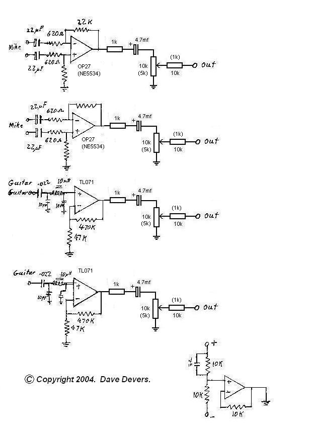
The mixer is extremely useful for direct input (DI) of guitars and basses into soundcards or other mixers, allowing for the utilization of channels on mixers that lack microphone inputs. It is particularly beneficial for one or two guitarists...
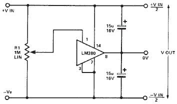
A simple split power supply circuit can be designed using the schematic diagram based on the LM380 audio power integrated circuit (IC). The output voltage regulation is dependent on the circuit feeding the LM380. The power dissipation is approximately...
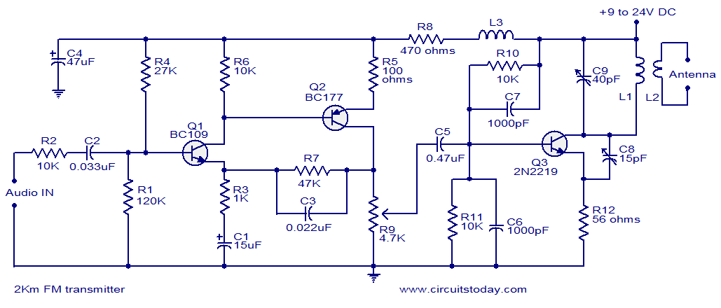
With a matching antenna, the FM transmitter circuit can transmit signals over a range of 2 kilometers. The transistors Q1 and Q2 form a highly sensitive preamplifier stage. The audio signal to be transmitted is coupled to the base...
This video transmitter circuit operates on the UHF channel frequency of 470-580 MHz, specifically channels 21-34. It can transmit video signals over distances ranging from 30 to 100 meters when using a cable length of 10 to 20 cm....