
Guitar Microphone Mixer Electronic Audio Kit for musicians

The mixer design incorporates a dual-board approach to accommodate different audio input requirements. The first board, optimized for guitar amplifier inputs, features a straightforward layout that allows for easy integration with standard guitar setups. The second board, tailored for soundcard inputs, provides enhanced flexibility with separate outputs to facilitate direct connections to digital audio workstations or recording interfaces. This separation is crucial for users who require clean, unprocessed signals for further manipulation in software.
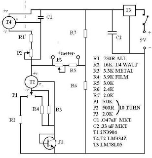
The operational amplifiers utilized in the design are selected for their low noise characteristics, which are essential for maintaining audio fidelity. The biasing scheme, employing a voltage divider, ensures that the op-amps operate within their optimal range, minimizing distortion and enhancing signal integrity. The option to replace one of the resistors with a zener diode is a valuable modification for users seeking to optimize noise performance in consistent supply voltage scenarios.
In terms of assembly, the PCB layouts are designed for ease of soldering and modification. The ability to rearrange components and break tracks provides a level of customization that caters to various user needs, whether for live performance or studio recording. The inclusion of balanced XLR outputs enhances compatibility with professional audio equipment, ensuring that the mixer can be seamlessly integrated into any audio setup.
Overall, this mixer represents a significant improvement over its original design, offering enhanced performance and versatility for musicians and audio engineers alike. The thoughtful design choices and potential for customization make it a valuable tool for anyone looking to enhance their audio mixing capabilities.The mixer is really handy for DI`ing guitars and basses into soundcards or other mixers and making use of channels on mixes that do not have mike in`s, it comes in handy for one or two guitarists that want to sing and play through one guitar amplifier as well. The printed circuit board will not be exactly the same as the one in the pictures, it wi ll be a bit better it has pots mounted on the broad in the same way as they are mounted on the board for the compressor. A second board design with a slightly different arrangement of the plots to suit lower impedances and separate direct outputs for soundcards will be included.
The difference between the two arrangements in respect to specifications is unnoticeable. The components on the first board may be rearranged and tracks broken to form the circuit provided by the second board or the board that best suits your application can be chosen. If enough interest is expressed in this project there maybe a ready-made PCB board available through this website.
The bias voltage for all of the opamps is derived from a voltage divider consisting of two 10K resistors that provide a mid voltage point, this voltage is then amplified through an opamp to lower noise introduced by the resistors, the output of this opamp is the bias input for the other opamps. If you are going to be using the same supply voltage all of the time then noise can be lowered a little more by replacing one of the resistors in the voltage divider with a zener diode, chose a zener that is close to half the supply voltage.
The mixer is really handy for DI`ing guitars and basses into soundcards or other mixers and making use of channels on mixes that do not have mike in`s, it comes in handy for one or two guitarists that want to sing and play through one guitar amplifier as well. Two printed circuit boards are described, the first is more suited for the input of a guitar amp, the second is more suited for the input of soundcards.
On the second board the outputs are connected together. To implement separate outputs break the track connecting the outputs and replace the 10k output resistors with 1k resistors. The PCB board diagrams are 200% photocopy them onto a transparency at 50% they work better this way! First make 50% copies on plane paper to check the size is going to be right. They can be printed directly to transparencies with the right ink and printers, many copying shops can do this for you.
Originally this mixer was one that I brought many many years ago, the original circuit consisted of 1 transistor, 7 resistors, 2 capacitors and 4 potentiometers, it was a bit noisy and had a gain close to unity. It had been sitting there for many years until a small mixer was needed, the mixer as it was, was just not good enough how it was.
So a new circuit and PCB board was designed and placed in the original chassis, a couple of balanced canon sockets were installed on the back, the original pots were too high in value so a couple of resistors were parallel across each one of them, this can be seen from the photo. Before all this it was a transistorised microphone mixer, what a beauty! Now it is a integrated circuit guitar microphone mixer. 🔗 External reference
Related Circuits
The circuit was intentionally designed without integrated circuits (ICs) and follows a traditional approach to achieve favorable harmonic distortion characteristics while avoiding the use of hard-to-find components. The amplifier can be powered conveniently using a 12V wall plug-in adapter....
There are many digital thermometers with ±1°C displays, but their accuracy is approximately ±1°C and they cannot be calibrated. A thermometer circuit was created using components available at a local electronics hobby shop, providing an educational experience. For a...
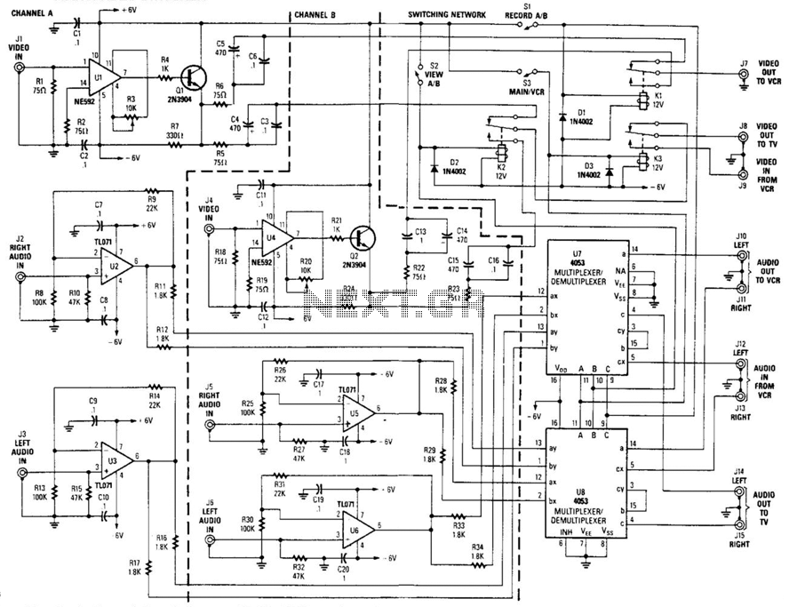
This circuit is a two-channel baseband video switcher. Buffer amplifiers U1/Q1, U4/Q4, and associated components produce a buffered 75-ohm video signal, which is routed to the switching network K1/K2/K3. Relay K1 selects either of the two video amplifiers and...
The April 1955 issue of Popular Electronics magazine features a cover illustration of a gentleman playing a homebuilt Theremin. Theremins are among the earliest electronic musical instruments, invented in the 1920s by Russian inventor Leon Theremin. The instrument is...
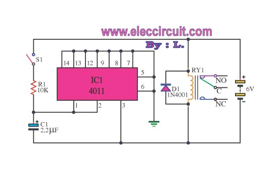
This circuit illustrates the use of the 4011 integrated circuit (IC) for a surge protection electronic circuit diagram. Features include the ability to delay the activation of other appliances connected to the output. The 4011 IC is a quad 2-input...
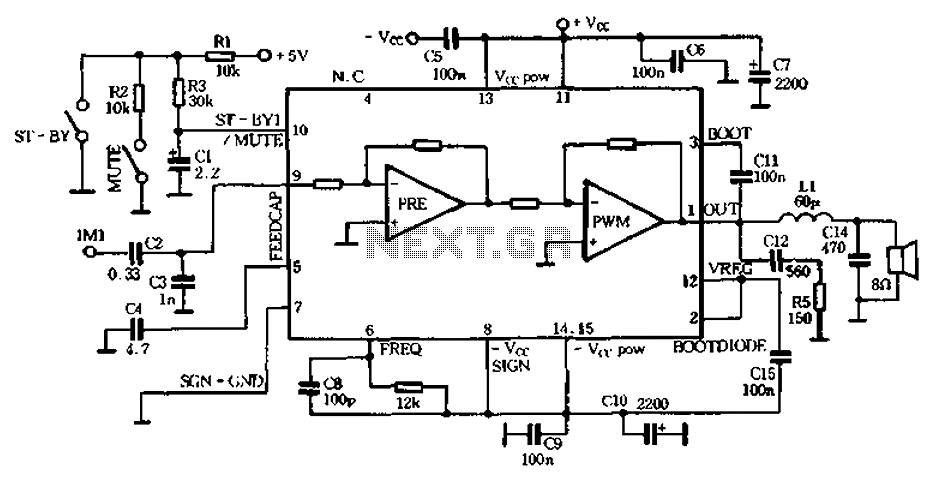
The PWM Class D audio amplifier has been the subject of exploration and reporting for over half a century. This technology is particularly attractive due to its high output efficiency, typically exceeding 85 to 90%. High output efficiency is...