
Simple UHF Video Transmitter

The video transmitter circuit is designed to operate within the UHF frequency range, which is suitable for various video transmission applications. The operating frequency of 470-580 MHz allows for clear transmission with minimal interference, making it ideal for remote video monitoring or broadcasting. The effective range of 30 to 100 meters is contingent upon the quality of the cable used, with shorter cables generally providing better signal integrity.
To enhance the transmitter's performance, particularly in environments with potential signal degradation, the integration of a bandpass filter is critical. This filter will ensure that only the desired frequency range is amplified, thereby reducing the likelihood of noise and interference from other signals. The supply voltage requirement of 9-15 volts allows for flexibility in power source selection, accommodating both standard power supplies and battery options. Utilizing a 9V battery can provide a convenient and portable solution, while a switching power supply may offer improved efficiency and lower noise levels.
When assembling the circuit, attention must be paid to the coil dimensions, as these are pivotal in determining the operational frequency of the transmitter. The coil acts as an inductor that resonates at the desired frequency, and its size and number of turns directly influence the inductance value. Careful calculations and adjustments may be necessary to ensure that the coil is properly tuned to the operating frequency, which will ultimately affect the quality and range of the transmitted signal.
In summary, this video transmitter circuit is a versatile solution for UHF video transmission, requiring careful consideration of component specifications and configurations to achieve optimal performance.Here`s video transmitter circuit is working on the UHF channel frequency 470-580 MHz channel 21-34. This video transmitter can radiate as far as 30-100 meters by using a cable 10-20 cm. If you have a plan to amplify this video transmitter`s signal, please make a good bandpass filter. This video transmitter requires supplies voltage of 9-15 volt. H owever, you can also use a 9v batteries. Better result on low signal noise, use switching power supply. This is an important thing to remember for building of the video transmitter circuit is that the dimensions of coil size to match the frequency of the desired work. The value of the spindle is making coil as follows: 🔗 External reference
Related Circuits
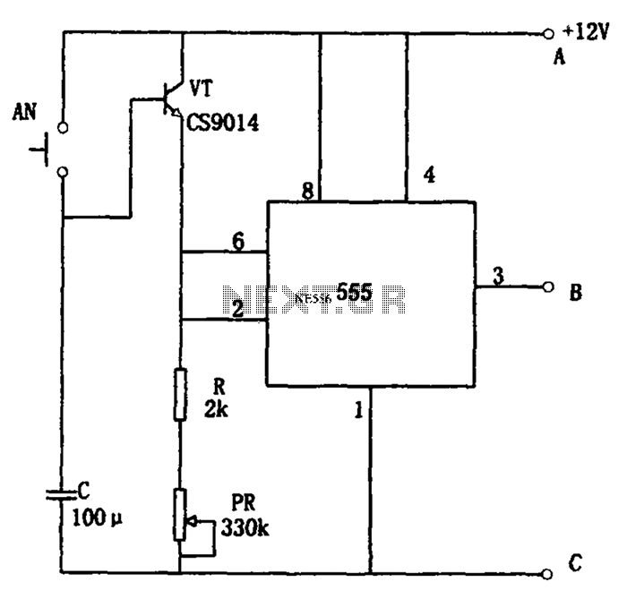
The circuit features a straightforward long timing mechanism. Activating switch AN initiates the timing process, while tone PR allows for timing adjustments. The timing range spans from 3 minutes to 220 minutes. With a capacitance value of 2200 µF,...
A 200-watt class-E AM transmitter designed for non-sanctioned broadcasting at a frequency of 1710 kHz. The schematic includes a negative peak limiter, an over-modulation indicator, a linear scale directional wattmeter, as well as power supply and antenna circuits. The 200-watt...
Take care with transmitter circuits. It is illegal in most countries to operate radio transmitters without a license. Although only low power this circuit may be tuned to operate over the range 87-108MHz with a range of 20 or...
This simple water detector circuit utilizes alternating voltage to prevent electrode corrosion. It is easy to construct and employs N1 as a trigger Schmitt gate to generate the AC signal. When a conductive substance, such as an aqueous solution,...
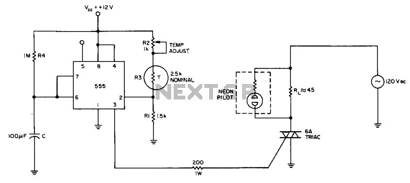
The internal comparator of the 555 timer, combined with a thermistor, creates a low-cost temperature controller. Resistor R2 establishes the temperature trip point. The 555 timer is a versatile integrated circuit widely used in various applications, including timers, oscillators, and...
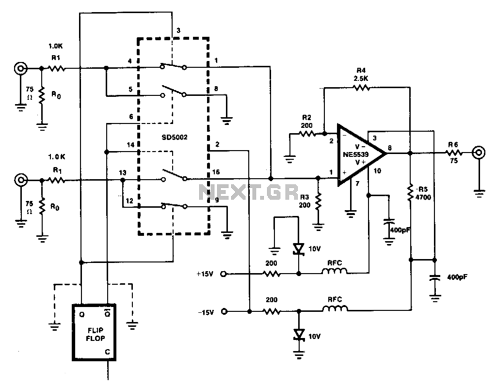
This figure illustrates a one-of-two switch featuring a summing amplifier. The video source's line can be terminated either externally or internally to switch RO. With this termination resistor, a load change of less than 10 ohms will be perceived...