Long-Range IR Transmitter

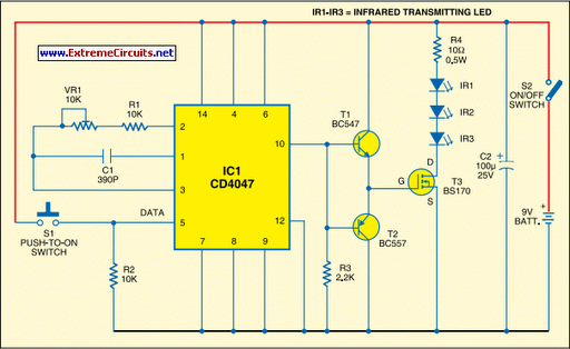
Most IR remotes operate reliably within a range of 5 meters. Designing an IR transmitter for reliable operation over a longer range, such as 10 meters, increases circuit complexity. To double the range from 5 meters to 10 meters, the transmitted power must be increased fourfold. For a highly directional IR beam, an IR laser pointer can be utilized as the IR signal source, which is readily available in the market. However, the narrow beam from the laser pointer requires careful handling, as any slight movement may alter the beam orientation and result in loss of contact. A simple circuit can achieve a considerable range by employing three infrared transmitting LEDs (IR1 through IR3) in series to enhance radiated power. To further improve directivity and power density, the IR LEDs can be assembled within the reflector of a flashlight. The circuit efficiency is enhanced by using a MOSFET (BS170) as a switch, instead of a standard transistor. To prevent voltage dips during on/off operations, a 100 µF reservoir capacitor (C2) is connected across the battery supply. This capacitor is particularly beneficial when the IR transmitter is powered by standard batteries, as it provides additional charge during switching operations. Due to the large gate-source capacitance of the MOSFET, a special drive arrangement using an NPN-PNP Darlington pair (BC547 and BC557 as emitter followers) is implemented to avoid distortion of the gate drive input. Data to be transmitted, which is CMOS-compatible, is used to modulate the 38 kHz frequency generated by the CD4047 (IC1). In this circuit, a tactile switch (S1) is employed to modulate and transmit the IR signal. The circuit should be assembled on a general-purpose PCB, with switch S2 used for power on/off control. Commercially available IR receiver modules, such as the TSOP1738, can be utilized for efficient reception of the transmitted IR signals.
The circuit design described utilizes a series configuration of three infrared LEDs to significantly increase the emitted power, thereby extending the operational range. The use of a MOSFET (BS170) as a switching element enhances the efficiency of the circuit compared to conventional transistors, as it can handle higher currents with lower on-resistance. The 100 µF capacitor (C2) plays a crucial role in stabilizing the power supply, ensuring that the circuit maintains consistent performance during rapid switching events, which is particularly important in battery-powered applications.
To improve the directivity of the IR beam, the assembly of the infrared LEDs within a flashlight reflector is a practical approach. This configuration focuses the emitted light into a narrower beam, increasing the effective range and ensuring that the signal remains strong over longer distances. The incorporation of a Darlington pair (BC547 and BC557) for driving the MOSFET is essential for providing sufficient gate drive current while minimizing distortion, ensuring that the modulation of the IR signal remains accurate.
The modulation of the 38 kHz signal generated by the CD4047 is a standard technique in IR communication, allowing for effective data transmission while minimizing interference from ambient light sources. The tactile switch (S1) serves as a simple user interface for initiating the transmission, while switch S2 provides convenient power control. The choice of a TSOP1738 IR receiver module for signal reception is advantageous due to its high sensitivity and compatibility with the modulation scheme employed, facilitating reliable communication in various applications. Overall, this circuit design represents a robust solution for extending the range and reliability of IR communication systems.Most of the IR remotes work reliably within a range of 5 metres. The circuit complexity increases if you design the IR transmitter for reliable operation over a longer range, say, 10 metres. To double the range from 5 metres to 10 metres, you need to increase the transmitted power four times.
If you wish to real i se a highly directional IR beam ( very narrow beam), you can suitably use an IR laser pointer as the IR signal source. The laser pointer is readily available in the market. However, with a very narrow beam from the laser pointer, you have to take extra care, lest a small jerk to the gadget may change the beam orientation and cause loss of contact. Here is a simple circuit that will give you a pretty long range. It uses three infrared transmitting LEDs (IR1 through IR3) in series to increase the radiated power. Further, to increase the directivity and so also the power density, you may assemble the IR LEDs inside the reflector of a torch.
For increasing the circuit efficiency, a MOSFET (BS170) has been used, which acts as a switch and thus reif a transistor were used. To avoid any dip during its on`/off` operations, a 100 µF reservoir capacitor C2 is used across the battery supply.
Its advantage will be more obvious when the IR transmitter is powered by ordinary batteries. Capacitor C2 supplies extra charge during switching on` operations. As the MOSFET exhibits large capacitance across gate-source terminals, a special drive arrangement has been made using npn-pnp Darl ington pair of BC547 and BC557 (as emitter followers), to avoid distortion of the gate drive input. Data (CMOS-compatible) to be transmitted is used for modulating the 38 kHz frequency generated by CD4047 (IC1).
However, in the circuit shown here, tactile switch S1 has been used for modulating and transmitting the IR signal. Assemble the circuit on a general-purpose PCB. Use switch S2 for power on`/off` control. Commercially available IR receiver modules (e. g. , TSOP1738) could be used for efficient reception of the transmitted IR signals. 🔗 External reference


