
Long wave radio and medium wave radio receiver using TBA120

The tuning stage operates by utilizing the properties of the ferrite bar, which enhances the inductance and sensitivity of the tuning coil (L2). The double diode varicap allows for voltage-controlled tuning, enabling adjustments to the resonant frequency of the circuit to match the desired radio frequency. The transistor (T1) serves as a buffer, isolating the tuning stage from the modulator while maintaining a high input impedance, thus minimizing signal loss.
The active antenna configuration is designed to improve reception by amplifying weak signals before they reach the demodulator. The TBA120 modulator integrates the necessary components to process the amplified signal and convert it into audio frequencies. The feedback mechanism ensures stability in the circuit operation, preventing oscillations that could degrade performance.
Coil L1, with its specified number of turns and wire gauge, is critical for achieving the desired resonant characteristics for both long-wave and medium-wave bands. The physical dimensions of the ferrite bar are optimized for these frequencies, ensuring efficient signal capture and amplification. The placement of the feedback loop at a quarter turn from the ground end of the coil is crucial for maintaining the desired phase relationship, which enhances the overall performance of the tuning stage.
Overall, the described circuit is a sophisticated design that effectively combines an active antenna and a tuning stage, ensuring high-quality reception of long-wave and medium-wave signals. The careful selection of components and their configuration contributes to the circuit's ability to function efficiently in various reception conditions.Tuning stage of this long wave radio and medium wave radio receiver also serves as active antenna that can be favorably positioned to get the best reception possible. Circuit is completely separate from the receiver, which consists of demodulator that provides audio-frequency output.
Plastic case of the antenna input circuit contains a tuning coil designed on a ferrite bar (L2) and a double diode varicap. Antenna signal is transmitted to the tuning stage via a transistor (T1) repeatedly emitter ensuring a high impedance output signal to the modulator. Received signal is amplified by the stage forming active antenna, but a part of the integrated circuit forming TBA120 modulator.
L2 coil emitter serves as a shock to L3 disengages T1 and voltage supply agreement, and thereby prevents shorting the RF output signal of the active antenna. L4 does the same thing for the demodulator. With the exception of L1, coils can be used for standard shocks coils. L1 consists of 250 turns of enamelled copper wire of 0. 2 mm diameter, long-wave range, and 80 turns of enameled copper wire of 0. 3 mm diameter (for medium waves) that is wrapped on a ferrite bar length about 20 cm and a diameter of 10 mm.
Positive feedback loop is connected to an outlet of the coil located at one quarter the number of turns from the end of the ground. 🔗 External reference
Related Circuits
For basic requirements, square wave inverters can be utilized as they are simple, low-cost, and easy to construct. However, pure sine wave inverters are preferred for driving inductive loads. This document discusses a simple low-power square wave inverter using...
To control 40 LEDs using a single PIC 18F2455 microcontroller, the LEDs were organized into a configuration of four columns, each containing 10 rows of LEDs. Each LED in a column was connected to a separate pin on the...
A high-frequency waveform generator is highly beneficial for electronic experimentation and design. This circuit generates sine wave oscillations; however, it can be modified to produce triangle or square wave functions. The frequency can be controlled using current. By disconnecting...
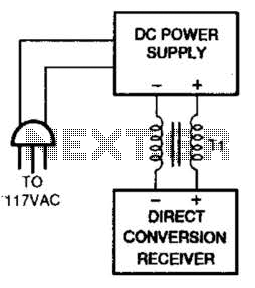
One solution for AC power line hum and ripple, which is caused by leakage current, is to utilize a well-regulated and filtered 9 to 18 VDC power supply that incorporates a balancing choke (Tl in this illustration) between the...
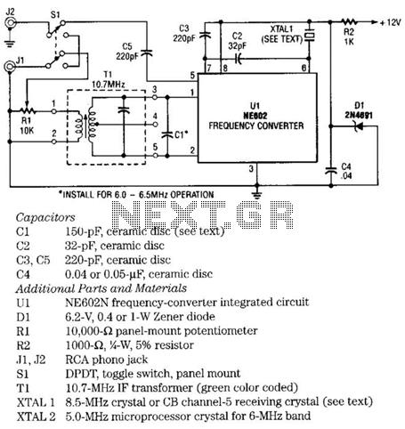
The NE602 chip, U1, contains oscillator and mixer stages. The mixer combines the oscillator signal with the input RF signal to produce signals whose frequencies are the sum and difference of the input frequencies. For example, an 8.5-MHz oscillator...
The simple FM radio circuit was overlooked during the transition from vacuum tubes to transistors. In the late 1950s and early 1960s, several construction articles were published on building a straightforward superregenerative FM radio. After extensive research into these...