
Loop Antenna For 3.5 Mhz

The schematic incorporates a variety of components that contribute to the functionality of the loop antenna design. The capacitors (C1 through C5) serve various purposes, including tuning and impedance matching, which are critical for optimizing the antenna's performance across the desired frequency range. The silver-mica capacitor (C1) is particularly valuable for its stability and low loss at high frequencies, while the preset (C2) and variable capacitors (C3 and C4) allow for fine-tuning of the antenna's resonance.
The moving coil meter (LB808) provides visual feedback on the antenna's performance, enabling the user to monitor the standing wave ratio (SWR) or power levels. The HF silicon diode (D) serves as a rectifier or detector, allowing for signal processing within the circuit. The resistor (R) is included for current limiting or biasing, ensuring that the circuit operates within safe parameters.
Inductors L1 and L2 are designed to create the necessary magnetic fields for resonance. L1, constructed from PVC-covered stranded wire, is designed for high voltage and current handling, while L2, made from tinned wire, provides additional inductance to the circuit. The RG58 coaxial cable serves as the feedline, connecting the antenna to the transmitter and minimizing signal loss.
The enclosure is constructed from an ABS box, providing durability and protection for the internal components. The terminal blocks facilitate easy connections for wiring, while the insulated spacers ensure that components are securely mounted and electrically isolated where necessary. The wooden support structure adds stability to the overall assembly, allowing for a robust design that can withstand various environmental conditions.
This loop antenna is particularly advantageous for portable operations or in situations where larger antennas cannot be deployed. Its compact design and efficient construction make it a versatile solution for amateur radio enthusiasts and those requiring effective communication on the 80-meter band. C1 = 3 750 pF 500 V silver-mica capacitor. C2= 100 pF preset capacitor (Jackson C803). C3 = 75 pF variable capacit or (Jackson C809), plus knob. C4 = 12.7 pF variable capacitor (Jackson C16), plus knob. C5 = 22 nF mica capacitor. = 250 f.s.d. 40 40 mm moving coil meter (Maplin LB808). D = HF silicon diode. R = 1 kft resistor (see text). L1 = 51/e turns of PVC covered stranded 7/0.2 mm wire. Outside diameter: 1.2 mm, 1 kV/1.5 A rating (see text). L2 = 13 turns 16SWG tinned wire, 1 inch internal diameter. Feedline = 46 inch RG58 coaxial cable, plus plug to suit transmitter. Box = ABS box type MB3,118 96 45 mm. Maplin ref. LH22. Terminal blocks = qty. 4 12-way 2 amp terminal block. Maplin ref. FE78. Spacers = qty. 3 insulated spacer type M3, 30 mm long, Maplin ref. FS40T. Spokes = qty. 4 8-foot lengths of 5/ 1/ inch molded hardwood (DIY store). Vertical support = 23 0.8 0.8 inch wood (DIY store). Wood base = 12x8x0.5 inch plywood or similar 21/2 inch steel support bracket. elektor electronics usaFig. 4-1 (b) 1.4 lengths molded hardwood 30" x^/ax 1/4". Varnished. 2BA holes drilled in the centre. Glued and bolted together. 2.8 off 6-way 2-amp polythene terminal blocks used as insulated wire spacers. 3.5Ve turns of PVC stranded wire (for specs see components list). 4.See Fig. 3. 5.Wood vertical support 23" 0.8" 0.8", wood stained. 6.2" x2BA bolt. 7.Box front vertical support, 4V2" x1/2" 3/4", wood stained. 8.Wood base 12" 8" xW (for similar), wood stained. 9.21/2 steel support bracket behind wood vertical support. 10. Drilled and secured with glue and c/s wood screws. Note: "= inch =2.54 cm. Suitable for receiving or transmitting (10 W or less) on the 80-m band, this loop antenna might be helpful when an outside antenna is not possible.
Related Circuits
These parameters are expected with an approximately 50% square wave up to frequencies of several MHz, and symmetric sine waves at higher frequencies. The primary limitation is based on the maximum clocking rate specification for the MM74HC6040 ripple counter...
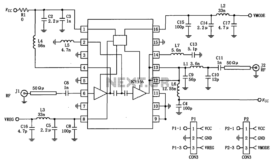
The circuit depicted in the figure is a 380MHz RF2175 linear amplifier application circuit. The radio frequency (RF) signal is input from pin 6 and is processed through a preamplifier, followed by a final power amplifier stage. The output...
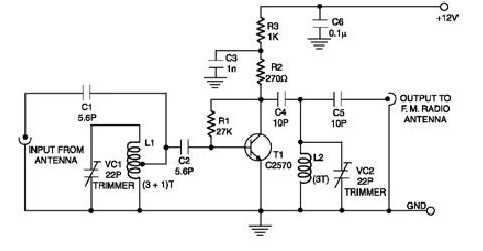
In the current era, various technologies are emerging at a rapid pace, with new innovations appearing approximately every three months. Among these advancements is the concept of a car radio that operates without an external antenna, inspired by the...
This low-power video transmitter is designed for remote control (R/C) applications, surveillance, or amateur radio purposes. It utilizes seven transistors within a crystal oscillator-multiplier RF power amplifier chain, along with a high-level video modulator. A supply voltage of 9...
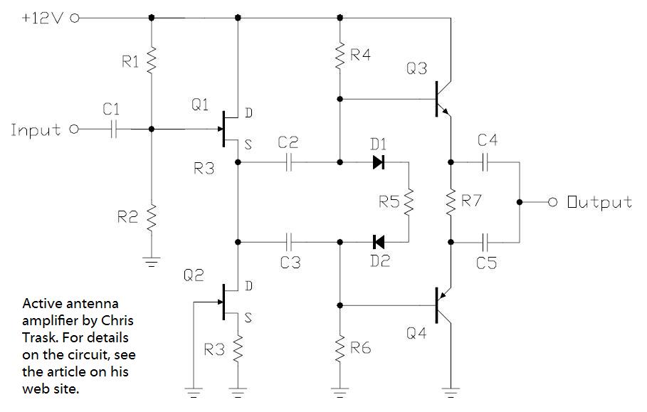
In the pursuit of effective small antennas, an active whip antenna was constructed. This compact vertical antenna is linked to a preamplifier, which serves to convert the high impedance of the 50-ohm receiver and coaxial cable. Various designs exist...
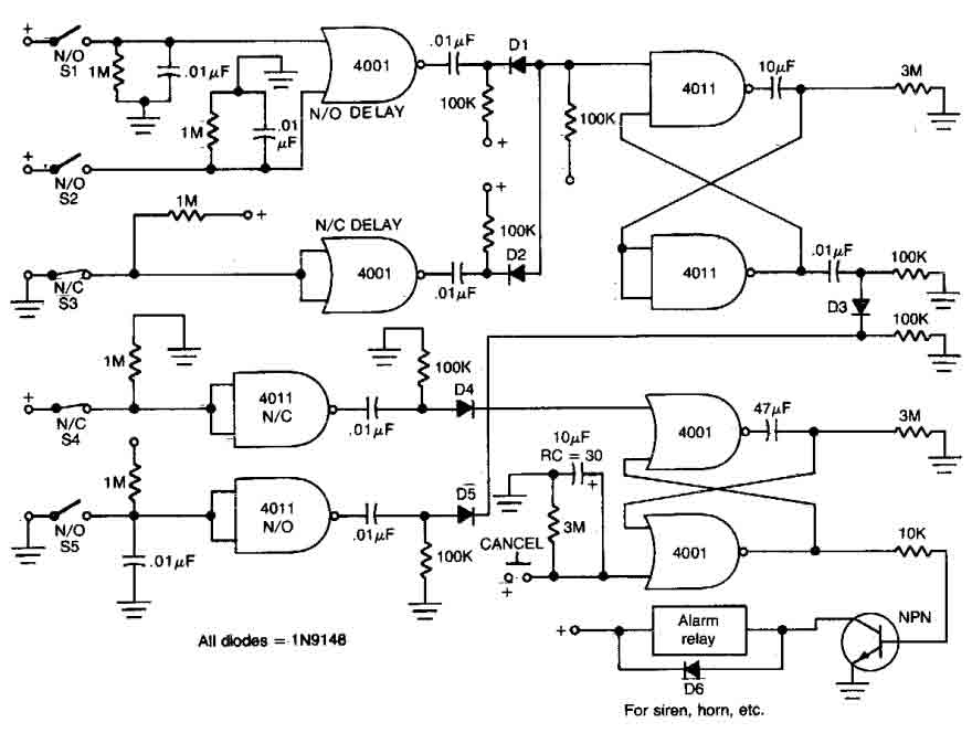
This circuit features open and closed loop contacts (switches 1, 2, 3) that activate the alarm, which remains activated for 5 to 10 minutes. The triggering delay for entrance and exit is set to 27 seconds. Additionally, this simple...