
Loudness Control
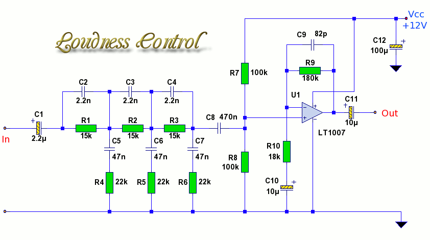
The described circuit serves as a loudness control system that compensates for the human ear's varying sensitivity to different frequencies at low volume levels. The design incorporates a three-stage passive RC filter, which effectively shapes the frequency response to enhance the bass and treble frequencies while reducing mid-range attenuation.
In the circuit, C1 functions as the input capacitor, ensuring that any DC voltage from previous stages does not interfere with the audio signal. The first stage, comprised of R1, C2, R4, and C5, is critical for frequency shaping. The components R2 and C1 create one branch of the frequency-dependent attenuator, designated as XL1, while C4 and R5 form the second branch, labeled XL2. The varying impedances of these branches across the audio spectrum allow for selective attenuation, ensuring that bass frequencies (20Hz) are boosted while treble frequencies (20kHz) are managed appropriately.
The cascading of additional stages amplifies the desired frequency response, creating pronounced peaks in the bass and treble regions. This design necessitates the use of an operational amplifier (op-amp) to provide the necessary gain, as passive components alone cannot achieve the desired amplification. The gain is controlled by resistors R9 and R10, with C9 serving to limit the high-frequency response, thereby preventing distortion at frequencies above 20kHz.
The choice of op-amp is crucial for achieving low noise and high fidelity in audio applications. The LT101 is specified for its performance, but alternatives such as the LF071 or NE5534 can be utilized if necessary. The circuit design and its performance characteristics can be simulated with software such as LTspice, allowing for thorough analysis and optimization before physical implementation.When listening to music at low volume levels, bass and treble frequencies are attenuated more than mid frequencies. This loudness control alters the frequency response curve to correspond roughly with the equal loudness characteristic of the ear.
The circuit shown, is for a single channel, so for a stereo system, two such units should be built. Th is circuit has a boost of 13dB at 20Hz and approximately 9dB at 20kHz. This circuit uses a three stage, passive, RC filter to tailor the frequency response, followed by an op-amp in non-inverting mode to provide the gain. The frequency response is shown below: C1, is the input capacitor, and blocks any DC from preceding stages.
R1, C2, R4, C5 are the first stage of a frequency shaping network. Each stage behaves as a frequency dependant attenuator and is easier to understand with the following diagram: R2 and C1 form one branch of an attenuator redrawn as XL1, and C4 and R5 form the second branch, equivalent to XL2. Across the audio spectrum, the impedance of XL1 and XL2 will vary, offering different amounts of attenuation at different frequencies.
The impedance of C2 is chosen at the treble frequency, 20KHz to be small compared to R2, and at the bass frequency, 20Hz, C5 is chosen to have a high impedance. The result is a constantly changing impedance network, as the effective values of XL1 and XL2 vary. You can think of the network as a frequency dependant attenuator, and the frequency response of this single network is shown below: Cascading two more of the same stages, results in a more pronounced peak at the bass and treble frequencies.
As all three stages are passive, the op-amp is needed to provide the necessary gain. Gain in the op-amp is set by R9 and R10, C9 in parallel with R9 rolls off the high frequency response above 20kHz. The op-amp is made by Analog Devices, type LT101. If not available, other low noise op-amps can be used instead such as LF071, NE5534, etc. All plots made with LTspice, link to the yahoo group below. 🔗 External reference
Related Circuits
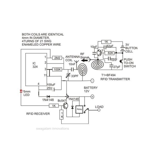
Constructing an RFID access control circuit at home and witnessing its functionality can be a remarkable experience. While the circuit may not be considered high-tech, its low cost combined with the satisfactory results achieved demonstrates a significant level of...
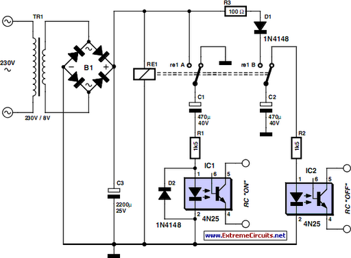
The request for assistance came from an elderly lady in a retirement home. In her room, the light switch by the door and the pull cord above the bed control the ceiling light fitting. However, she prefers to operate...
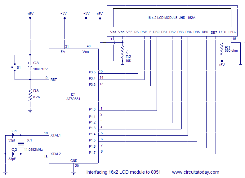
Interfacing a 16x2 alphanumeric LCD module with the AT89S51 microcontroller. The circuit diagram, theory, and program are included. JHD162 LCD module pinout and commands are provided. The integration of a 16x2 alphanumeric LCD module with the AT89S51 microcontroller involves several...
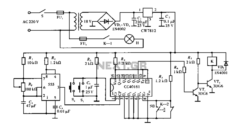
Corridor counter delay circuit for controlling lights. This circuit is tested and functional. When the circuit is energized, the 555 oscillator starts to oscillate. The CC40161 is cleared, and an integrating circuit composed of R3 and C5 transitions the...
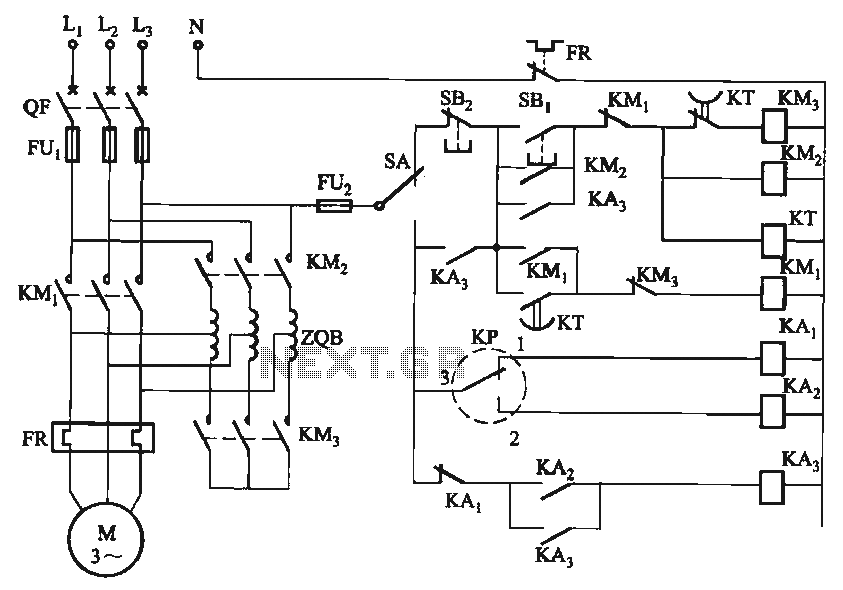
The circuit utilizes a motor auto-voltage transformer for starting. The motor auto-voltage transformer start circuit is designed to provide a controlled method for initiating the operation of an electric motor. This type of circuit is particularly beneficial in applications where...
The circuit of an FM Tracking Transmitter Circuit or Remote Control Transmitter Circuit is explained using a 555 IC and 2N4392 transistors. The FM Tracking Transmitter Circuit utilizes a 555 timer integrated circuit (IC) configured in astable mode to generate...