
make yourself this low cost rfid access control circuit at home

The RFID access control circuit typically consists of several key components: an RFID reader, RFID tags, a microcontroller, and a relay module. The RFID reader is responsible for detecting the RFID tags, which contain unique identifiers. Upon scanning an authorized tag, the reader sends a signal to the microcontroller, which processes the data and determines whether access should be granted or denied.
The microcontroller serves as the brain of the circuit, executing the programmed logic to compare the scanned tag's ID against a database of authorized IDs. If a match is found, the microcontroller activates the relay module, which can control an electronic lock or gate mechanism, allowing access. Conversely, if the tag is unauthorized, the relay remains inactive, preventing entry.
Power supply considerations are also crucial; the circuit typically requires a stable power source to ensure reliable operation. Additionally, incorporating status LEDs can provide visual feedback, indicating whether access has been granted or denied.
For enhanced security, the circuit can be expanded with features such as an alarm system or a logging mechanism to track access attempts. Overall, the RFID access control circuit stands as an efficient and cost-effective solution for managing access control in various applications.Building a RFID access control circuit at home and seeing it actually work can be truly an amazing experience. Although the circuit is not a hi-tech one, but comparing its low cost with the fairly good results obtained simply proves its high degree of efficiency..
🔗 External reference
Related Circuits
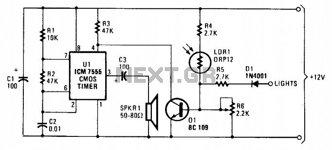
As dusk begins to fall, the sensor, which is a cadmium-sulfide light-dependent resistor (LDR), activates a small horn to provide an audible reminder to turn on the lights. The circuit can be turned off by simply switching on the...

An NPN bipolar transistor is typically utilized for relay switching, particularly with 12V coil-rated relays, as it helps maintain circuit separation. A diode is also added to prevent issues. The necessity of driving the relay with a transistor depends...
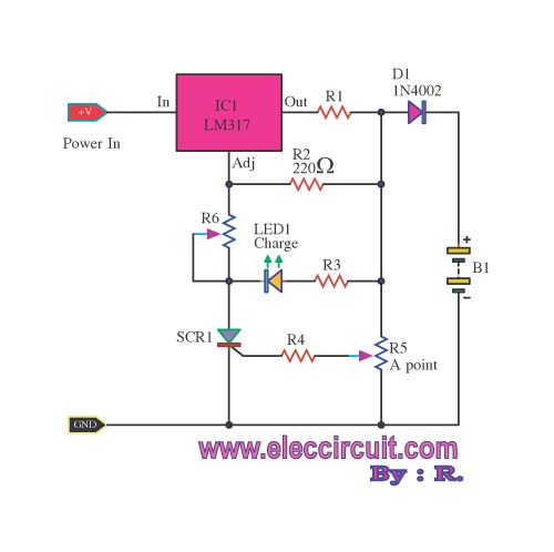
When building a lead-acid battery charger for a 6V or 12V battery, there are various methods available. One preferred option is the use of the IC LM317. The LM317 is a versatile adjustable voltage regulator that can be effectively utilized...
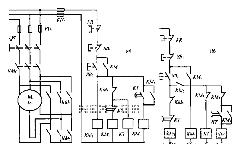
A star-delta switch is utilized for starting circuits, commonly depicted in Figure I-5 (a) of the knife wiring. While this method is effective, it poses security risks. When the motor starts, it can create significant voltage fluctuations that may...
Circuit of a crystal-controlled FM transmitter. The circuit utilizes a crystal oscillator and several power amplifier stages to enhance output power. The crystal-controlled FM transmitter circuit is designed to generate frequency-modulated signals with high stability and precision. At the core...
The circuit diagram presented is a highly sensitive wireless relay switch designed to control home appliances such as flush systems and hand dryers. This wireless switch operates without the need for a remote control. It functions by simply moving...