
Corridor counter delay circuit for controlling lights

The corridor counter delay circuit is designed to manage lighting in corridor areas efficiently. The circuit utilizes a 555 timer configured in astable mode to generate a pulse-width modulation signal, which controls the timing of the relay operation. The CC40161 is a binary counter that keeps track of the number of oscillations produced by the 555 timer, allowing for the integration of time delays before activating the relay.
Upon energizing the circuit, the 555 timer initiates oscillation, producing a square wave output. This output is fed into the CC40161, which counts the pulses. The R3 and C5 components form an RC time constant that determines the integration time, effectively controlling how long the circuit will wait before responding to the count.
When the binary count reaches a predetermined value, the CC40161 activates the relay K. This relay has two sets of contacts: K-1, which is normally open, closes to power the lights (H), and K-2, which is normally closed, opens to disconnect the circuit from the power source, ensuring that the lights are only on for the required duration. The output of the CC40161 going high signals that the counting process is complete, allowing for a controlled and efficient lighting solution in corridor settings.
This design minimizes energy consumption by ensuring that lights are only activated when necessary, thus providing both functionality and efficiency in corridor lighting management.Corridor counter delay circuit for controlling lights This circuit is tested and functionable. When the circuit is energized, the 555 oscillator starts to oscillate, CC40161 is cleared R3, C5 integrating circuit composed of the state and into the count. Relay K to be energized, K-1 is closed, lights H lit, while K-2 normally closed contacts disconnect, C C40161 of E, goes high.
Related Circuits
A buzzer circuit utilizes a PIC microcontroller to drive a piezo buzzer. The microcontroller is a low-power processor that is ideal for portable and compact devices where battery conservation is essential. The buzzer circuit employs a PIC microcontroller, which serves...
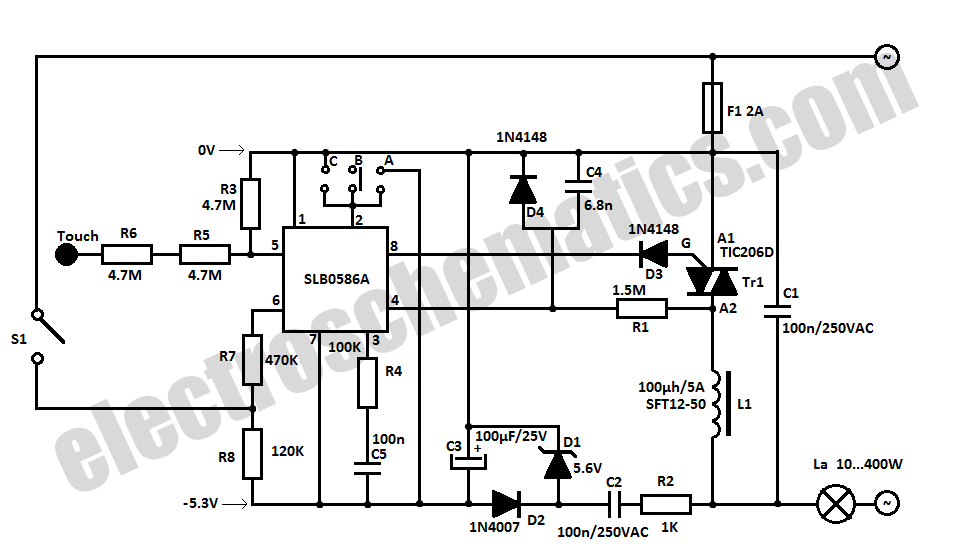
The SLB0586A integrated circuit from Siemens can be utilized to create a simple touch light dimmer circuit, allowing for the adjustment of lamp intensity. When paired with a TIC206D triac, this setup enables smooth regulation of light intensity for...
Here, S1 and S2 are normally open, push to close, press button switches. The diodes can be red or green and are there only to indicate direction. You may need to alter the TIP31 transistors depending on the motor...

This circuit adds a power-down function to analog I/O ports, such as the AD7769 and AD7774. Additionally, the diodes typically required to protect the devices against power-supply mis-sequencing can be eliminated. In this design, MOSFETs Q1 and Q2 switch...

This is a 300 W RF amplifier designed for FM transmission, capable of operating within the frequency range of 88 to 108 MHz. The amplifier utilizes two TP9383 transistors, enabling it to deliver up to 300 W of output...
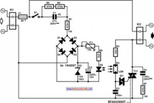
The following circuit illustrates an Automatic Light Dimmer Circuit Diagram utilizing a 1N4007 diode. Features include integration within a wall-mounted box. The Automatic Light Dimmer Circuit is designed to adjust the brightness of a light source automatically based on ambient...