
Loudness control circuit

This loudness volume control circuit is designed to enhance the listening experience by adjusting the perceived loudness of audio signals. The circuit configuration typically includes a potentiometer that serves as a variable resistor, enabling users to modify the resistance and, consequently, the loudness level. The choice of components, including resistors (Rc, R1, Rz) and capacitors (C), plays a critical role in defining the circuit's frequency response and overall performance.
In scenarios where the source's internal impedance is much smaller than Rc, the circuit effectively minimizes signal loss and distortion, ensuring that audio fidelity is maintained. The high load impedance (Rp) further contributes to this by allowing the circuit to operate efficiently without overloading the source. The selection of a high-value capacitor (C) is crucial, as it allows the circuit to filter out higher frequencies, thereby enhancing the low-frequency audio response.
When tuning this circuit, careful consideration must be given to the values of the resistors and capacitor to achieve the desired loudness effect. The circuit can be implemented in various audio applications, including home audio systems, musical instruments, and professional audio equipment, providing users with a versatile solution for controlling audio loudness while preserving sound quality.Figure 1-87 is a good loudness volume control circuit, it uses an ordinary potentiometer, used element pieces are scarce, but the effect is quite remarkable. The electric road works is: when the internal impedance of the source is much much smaller than Rc, big load impedance Rp, and Rp is much greater than when I ruler and Rz, the capacitance C taken only high value, audio works for low audio can be regarded as open
Related Circuits
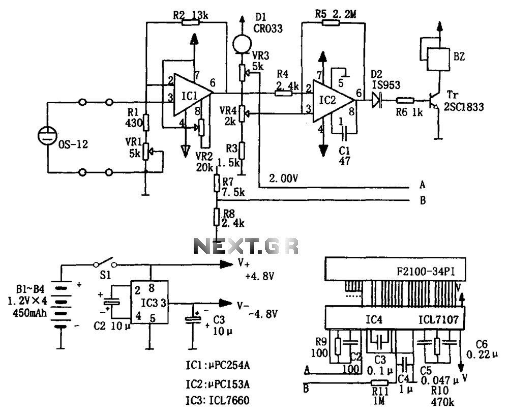
The portable hypoxia monitoring circuit comprises the oxygen sensor OS-12, a DC amplifier IC1, an A/D converter IC4, and a liquid crystal display F2100-34PI. Additionally, it includes a voltage comparator IC2 and a positive and negative power converter IC,...
The schematic presented is a project for a simple temperature sensor circuit, also referred to as a heat sensor circuit, which activates an LED in response to heat. The circuit is straightforward to construct and requires only a few...
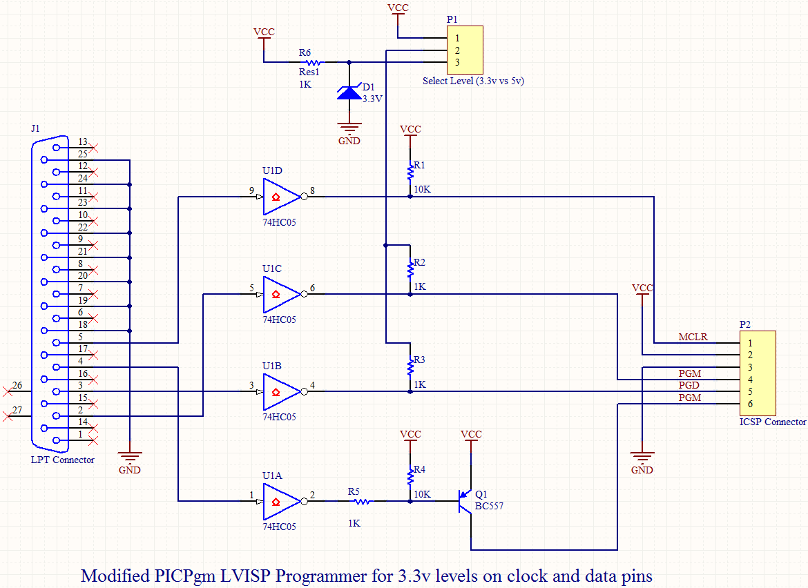
Microchip's PIC18F14K50 is an excellent choice, offering a wide range of features in a compact package at an affordable price. While focusing on the chip's numerous capabilities, a specific requirement for its flash programming was overlooked during the design...
This circuit illustrates a Go-No/Go Tester Circuit utilizing a 555 Timer IC. Features include a more advanced unit with a precise timed testing procedure. The Go-No/Go Tester Circuit is designed to evaluate components or assemblies by providing a simple pass/fail...
Many households still have tube-type television sets. Connecting one of these large televisions to a stereo system to enhance sound quality is generally straightforward, as numerous SCART to Cinch adapters are available in accessory stores. However, some television sets...
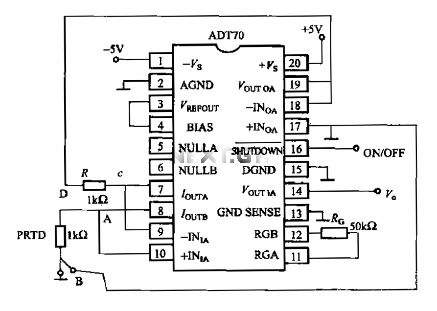
The AD170 basic electrical parameters include a temperature coefficient of 25 ppm/°C and a temperature measurement accuracy of ±1°C, with a maximum temperature range of -200°C to +100°C. The power supply required is +5V or -5V, and the operating...