
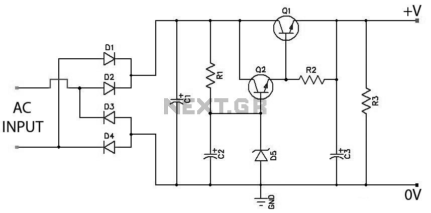
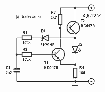
Low battery indicators with LED


The described circuit utilizes a pair of bipolar junction transistors (BJTs) configured to function as a current source with an LED indicator for battery discharge status. The circuit operates based on the relationship between the voltage across the base-emitter junction of the transistors and the supply voltage derived from a battery.
The first transistor (Tr1) is responsible for controlling the LED state based on the battery voltage. When the battery voltage falls below 5.78V, the base-emitter voltage of Tr2 is insufficient to keep it conducting, thereby turning Tr1 on and illuminating the LED. The LED used in this configuration is a green LED, which typically requires about 2.0V to conduct. The configuration also includes a zener diode (Zd) that stabilizes the voltage at a specific level, ensuring that the transistors operate within their intended parameters.
The resistors in the circuit, specifically R1 and R2, play crucial roles in defining the current through the transistors. R1 is selected to set the discharge current through Tr2, and its value must be chosen carefully to manage the power dissipation, especially when discharging a 9V battery at a current of 100mA, which results in a power dissipation of 900mW. Adequate thermal management, such as using a heatsink, is essential for the longevity and reliability of Tr2.
The adjustable potentiometer (47K) allows for fine-tuning of the base voltage applied to Tr2, enabling the user to set the threshold at which the LED will turn on or off. The voltage across the potentiometer and the fixed resistor (22K) is critical in determining the operational point of the transistors. By adjusting these values, the circuit can be calibrated to suit different battery chemistries or specific application requirements.
Overall, this circuit provides a simple yet effective means of monitoring battery discharge levels, utilizing basic electronic components to achieve a functional and adjustable LED indicator system.For a transistor to conduct, it requires a voltage of about 0.6 between its base and emitter. This voltage is applied from the wiper of the 47K pot. Now if the pot is at minimum, this voltage is across the 22K, so the 47K will have about 1.28v across it - or 1.88 across the pair. Add the 3V9 from the zener: this will require a battery voltage of 5.78v to just turn on the first transistor.
Above 5.78 the right hand transistor is turned on, the left hand is therefore off and the LED is also off. Below 5.78v the LED will therefore come on. A green LED has around 2.0v on it when it is illuminated. This value varies a bit with different manufacturers, but is usually pretty well matched within any batch. Add the base emitter voltage and you need 2.6v on the base of right transistor (i.e. across the 3K3) to turn on the transistor. 2.6v across 3K3 needs 9.1 across the supply rail. The two transistors form a current source. R2 conducts via Zd and supplies base current to Tr2. Tr2's collector current flows through R1 developing a voltage which turns Tr1 on. As Tr1 starts to conduct it pinches current that would otherwise turn Tr2 harder on, so the circuit balances at the correct current to just develop 0.6v across R1.
So the current is 0.6/R1. You chose R1 for the correct discharge currrent. Remember that to discharge a 9v battery at 100mA, Tr2 will dissipate 9 x 0.1, or 900 milliwatts. Choose a suitable transistor with a suitable heatsink! The current through R2 is defined by the battery voltage less the zener voltage so as the battery discharges, there will eventually come a voltage where the battery has fallen to the zener voltage (plus 0.6v across Tr2's base-emitter. The circuit is now completely off and the battery is discharged to the end level. Below this threshold voltage the transistor is off and the RED LED is on. Above this voltage the red LED is off. The threshold can be altered by altering the three resistors. 🔗 External reference
Related Circuits
Low Ripple Regulated Power Supply Circuit Diagram. This circuit can be employed in applications requiring high current with minimal ripple voltage, such as in high-powered class AB amplifiers where high-quality audio reproduction is essential. The low ripple regulated power...
One of the most interesting shields that can be mounted on the Arduino platform is the Ethernet shield. It enables numerous networking applications such as remote control of systems and users, web access, and data publication. The ease of...
This circuit allows an external 12V sealed lead-acid (SLA) battery to power a camcorder that typically operates with an internal 7.2V battery. Obtaining such batteries for older camcorder models can be challenging and costly. The circuit functions as a...
The diagram illustrates a lamp dimmer that gradually increases and decreases light intensity. This feature prevents sudden illumination, which can be a shock to the human eye, and also minimizes damage caused by inrush current when the lamp is...
This is a simple design of a single flashlight. This small circuit is within a half hour to build. The circuit operates from 4.5 to 12 V. Of course it is possible other than to drive an LED. More:...
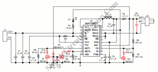
Switch mode circuits can implement a lead acid battery charger more efficiently. It can be constructed using the bq24105 battery charger controller. The bq24105 was originally designed to charge single, two, or three-cell Li-polymer and Li-ion battery packs. However,...