
Low Ripple Power SupplyCircuit

The low ripple regulated power supply circuit is designed to deliver stable voltage while minimizing voltage fluctuations, which is crucial in sensitive audio applications. The circuit typically includes key components such as a transformer, rectifier, filter capacitors, and a voltage regulator.
The transformer steps down the AC voltage from the mains supply to a lower AC voltage suitable for the application. The output from the transformer is then fed into a rectifier, which converts the AC voltage to pulsating DC voltage. Common rectifier configurations include full-wave or bridge rectifiers, which enhance efficiency by utilizing both halves of the AC waveform.
After rectification, the pulsating DC voltage is smoothed using filter capacitors. These capacitors charge during the peaks of the voltage and discharge during the troughs, effectively reducing ripple voltage. The choice of capacitor values is critical; larger capacitance values provide better filtering but may also increase the circuit's response time to load changes.
Finally, a voltage regulator is employed to ensure that the output voltage remains stable regardless of variations in load current or input voltage. Linear voltage regulators, such as the LM7812 for 12V output, or switching regulators, can be used depending on efficiency requirements and thermal considerations.
Additional components such as heat sinks may be necessary for the voltage regulator to dissipate heat effectively, especially under high load conditions. Bypass capacitors placed close to the regulator's output can further enhance stability and transient response.
In summary, this low ripple regulated power supply circuit is an essential design for applications demanding high fidelity and stable performance in audio amplification systems. Proper selection and arrangement of components ensure optimal operation and reliability in delivering clean power to sensitive electronic devices.Low Ripple Regulated Power Supply Circuit Diagram This circuit may be used where a high current is required with a low ripple voltage (such as in a high powered class AB amplifier when high quality reproduction is necessary ). PARTS LISTR12.. 🔗 External reference
Related Circuits
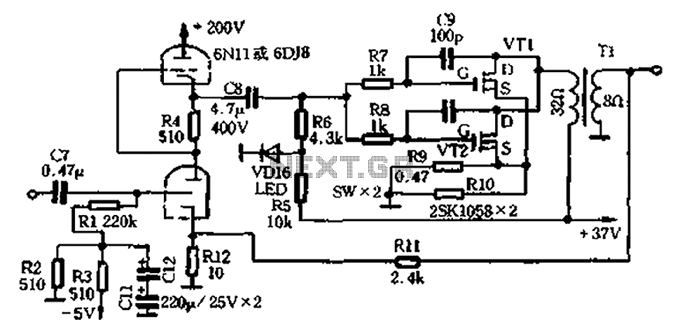
The amplifier circuit illustrated in Figure 2-25 features the following: (1) It utilizes a class 6N11 tube for parallel push-pull amplification, providing high-frequency response and an excellent signal-to-noise ratio. (2) The final stage of the semiconductor amplifier does not...
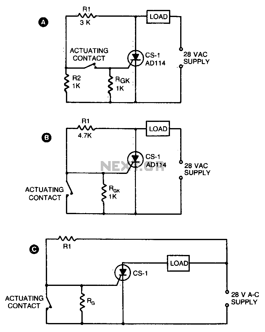
Two simple arrangements for resistive loads are shown in A and B. The circuit in A will provide load power when the actuating contact is closed, and no power when the contact is open. B provides the reverse of...
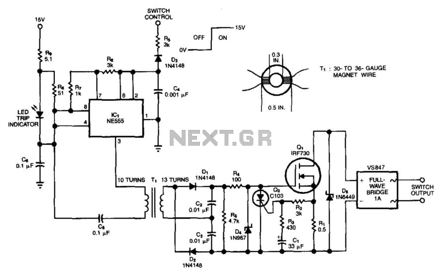
This solid-state switch detects and interrupts an overcurrent condition within 2 microseconds. It allows the circuit to float. IC1 operates at 150 kHz, and the full-wave doubler D1/D2 provides 15 V to the gate of Q1. An overcurrent sensed...
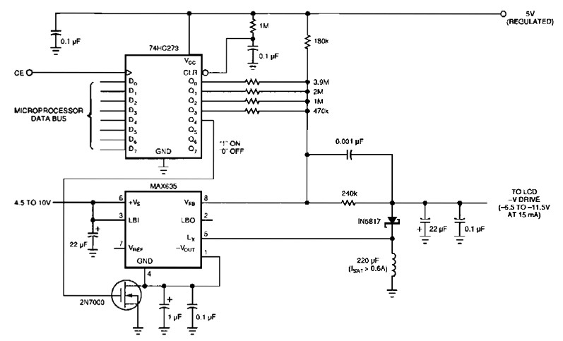
The following figure's switching regulator generates a negative voltage from the notebook battery supply. The microprocessor data bus drives a 4-bit DAC (74HC273), which can vary the regulator output between 6.5 to 11.5 V. This arrangement enables a staircase...
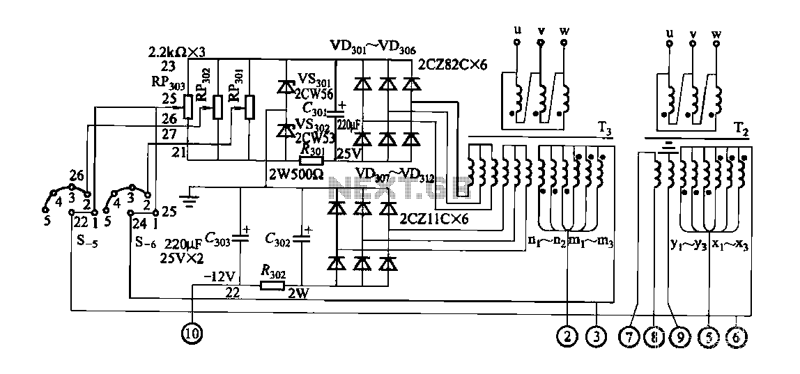
FGDF-3 is a three-phase low-temperature iron plating power supply circuit, while the KGDF-3 is a single-phase low-temperature iron plating power supply device that encompasses all the characteristics of the power supply unit. This design allows for an even distribution...
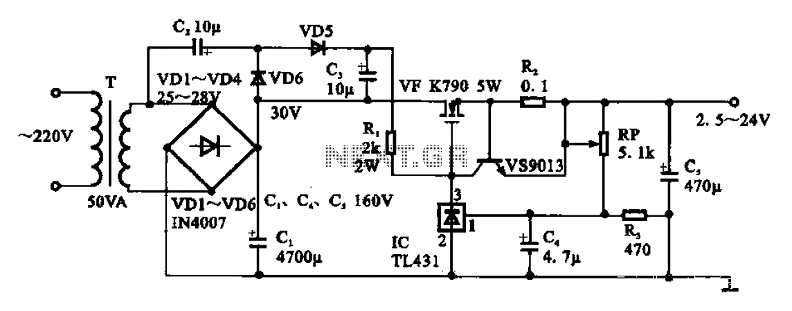
An adjustable DC power supply circuit is presented, consisting of a step-down transformer (T), a rectifier bridge (VD1 to VD4), and additional components. The voltage regulator circuit includes an adjustment potentiometer (RP, 5.1 kΩ), allowing the output voltage to...