
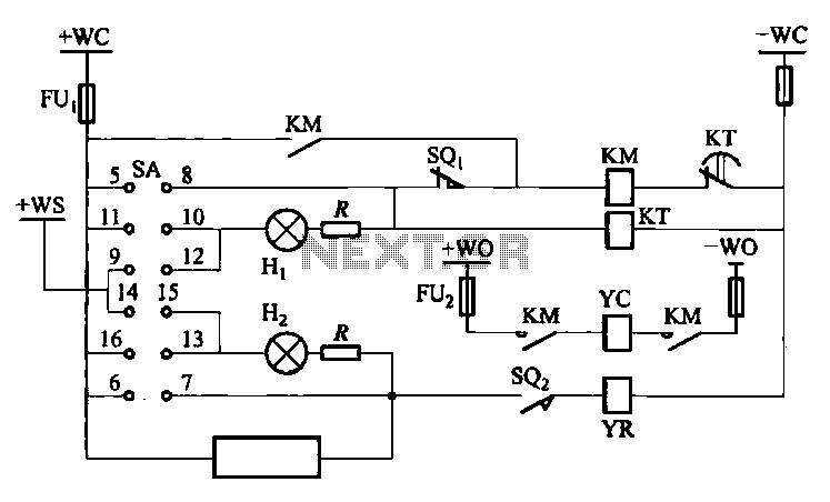
Double tube fluorescent lighting circuit

The double tube fluorescent lighting circuit operates by integrating two individual single-tube circuits into a cohesive system designed to enhance illumination levels. Each tube operates independently, allowing for a more efficient distribution of light compared to a single tube. The circuit typically includes components such as a ballast, which regulates the current flowing through the tubes, ensuring they operate at optimal efficiency while preventing flickering or overheating.
The installation of the double tube fluorescent lighting circuit involves connecting the two tubes in parallel or series, depending on the design requirements. In a parallel configuration, each tube receives the same voltage, providing uniform brightness, while in a series configuration, the voltage is divided between the two tubes, which may result in varied brightness levels.
The circuit is designed to accommodate standard fluorescent tubes, typically available in various lengths and wattages, allowing for flexibility in lighting design. Additional components may include starters, which help initiate the gas discharge process in the tubes, and switches for controlling the on/off state of the lighting system.
This type of lighting solution is commonly used in commercial and industrial settings where higher luminous output is essential for visibility and safety. The double tube fluorescent lighting circuit not only enhances brightness but also contributes to energy efficiency, making it a practical choice for extensive lighting applications. Proper installation and maintenance of this circuit are crucial to ensure longevity and optimal performance of the fluorescent tubes.Double tube fluorescent lighting circuit is shown. In some cases the need to improve twice, single-tube light can not meet the lighting requirements, double tube lighting. Phys ical installation is shown in a double tube lamp shown. Double tube fluorescent lighting circuit is a combination of two single-tube lamp circuit,
Related Circuits
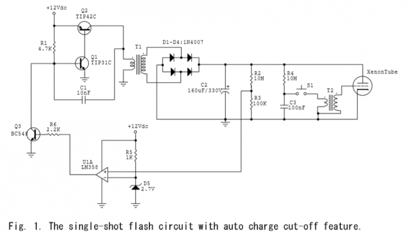
A voltage divider is created using resistors R2 (10MΩ) and R3 (100KΩ), which effectively reduces the voltage across capacitor C2 by a factor of approximately 100. The ground of C2 is connected to the inverter ground for reference. An...
The DW10M de-excitation type switch is based on the DW10 automatic air circuit breaker, transitioning from normally open to normally closed contact. The models available include DW10M-200, DW10M-400, and DW10M-600. The control circuit for this type switch is illustrated...
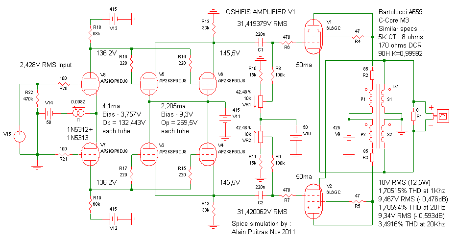
This is an effective amplifier design that is challenging to enhance. The results validate the 6DJ8 and 6L6GC Spice models, as the 6L6GC and 807 exhibit similar characteristics, yielding results closely aligned with the schematic. Utilizing the 1N5312 and...

Q1 is an audio amplifier, and U1 is utilized as a 31.5 kHz subcarrier, which is comparable to the 38 kHz FM multiplex. The pilot frequency is 15.734 kHz. In this circuit, Q1 serves as the audio amplifier, responsible for...
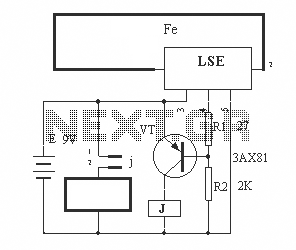
The circuit operation principle of the device illustrated in the figure is as follows: When the barbed wire is intact, the output pin of the LSE is high due to the absence of contact. Consequently, the transistor VT is...
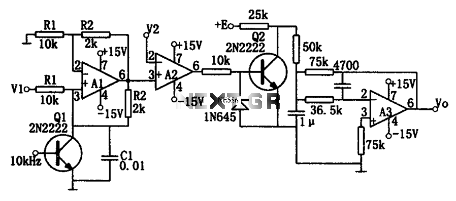
As illustrated in the dividing circuit diagram, A1 consists of a voltage-controlled current source, A2 functions as a voltage comparator, and A3 is configured as an active low-pass filter. When the time constant R1C1 is equal to the clock...