
Low frequency divider

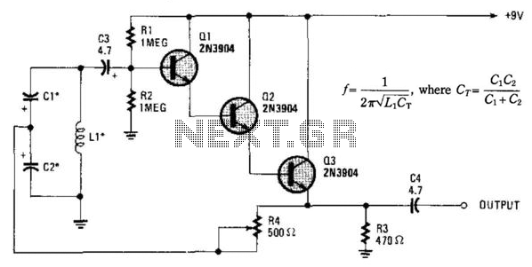
The described circuit employs capacitors C1 and C2 to create a voltage division mechanism influenced by the operation of a transistor Q1 and a Programmable Unijunction Transistor (PUT). The capacitors are initially in a discharged state, and when a positive pulse is applied to the base of Q1, both capacitors charge to a predetermined voltage, which is 10 volts in this scenario. The equal capacitance values of C1 and C2 facilitate a symmetrical charging and discharging process.
When Q1 is turned off, the capacitors undergo charging through resistor R3. The subsequent pulse at the base of Q1 causes C1 to discharge while C2 retains its charge. This sequence is crucial for the circuit's operation, as it allows C2 to reach the firing voltage of the PUT, leading to its activation. The firing of the PUT results in the discharge of C2, which in turn enables C1 to charge up to the line voltage, thereby creating a feedback loop that maintains the operation of the circuit.
The relationship between the input frequency and the capacitance values is critical for achieving the desired output frequency. The equation governing this relationship indicates that for a specific input frequency of 10 kHz and a voltage amplitude of 3 volts, certain capacitance values must be selected to ensure an effective division ratio, which is noted to be from 2 to 11 in the provided data. The operation of the circuit continues cyclically, with each cycle initiated by a positive pulse that prompts the discharge of C1, maintaining the overall functionality of the voltage division and timing mechanism.The ratio of capacitors Cl and C2 determines division. With a positive pulse applied to the base of Ql, assume that Cl = C2 and that Cl and C2 are discharged. When {31 turns off, both Cl and C2 charge to 10 volts each through R3. On the next pulse to the base of Ql, Cl is again discharged but C2 remains charged to 10 volts. As Ql turns off this time, Cl and C2 again charge. This time C2 charges to the peak point firing voltage of the PUT causing it to fire. This discharges capacitor C2 and allows capacitor Cl to charge to the line voltage. The input and output frequency can be approximated by the equation (Cl = C2) Cl For a 10 kHz input frequency with an amplitude of 3 volts, the table shows the values for Cl and C2 needed to divide by 2 to 11. As soon as C2 discharges and Cl charges, the PUT turns off. The next cycle begins with another positive pulse on the base of Ql which again discharges Cl.
Related Circuits
The BFP640 transistor is utilized for 1575 MHz Global Positioning Satellite (GPS) applications, specifically as a Low Noise Amplifier (LNA). The design objectives include a minimum gain of 16 dB, a noise figure of less than 0.6 dB, an...
This document outlines a basic circuit designed to power high impedance, high voltage, low current devices such as electroluminescent (EL) backlights and fluorescent tubes. The project originated from the need for a simple yet flexible inverter circuit for an...
In conventional white LED design, the Max1916 low-dropout bias supply for white LEDs serves as a high-performance alternative to simple ballast resistors. The Max1916 is an integrated circuit designed to provide a stable and efficient bias supply for white LEDs....
More: A comprehensive electronic schematic that outlines the design and functionality of a specific circuit is crucial for understanding its operation. The schematic should include components such as resistors, capacitors, diodes, transistors, and integrated circuits, along with their interconnections....
Essentially, this is a Hartley oscillator utilizing a triple-emitter follower, suitable for audio and low radio frequencies. The frequency is determined by the components, and at 1 kHz, a typical capacitor value would be 4.7 µF tantalum, although this...
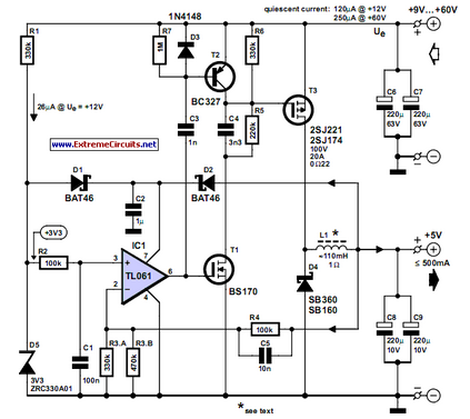
This circuit was developed to provide a 5 V output from the 24 V battery of a solar-powered generator. The circuit is designed to efficiently step down the voltage from a 24 V source to a stable 5 V...