
Low-Loss Step Down Converter

The circuit is designed to efficiently step down the voltage from a 24 V source to a stable 5 V output, which is essential for powering various low-voltage devices and components in solar applications. The primary component utilized in this design is a buck converter, which is known for its ability to convert a higher voltage to a lower voltage with high efficiency.
The buck converter operates by switching the input voltage on and off rapidly using a transistor. This switching action is controlled by a pulse-width modulation (PWM) signal, which adjusts the duty cycle to regulate the output voltage. An inductor is used to store energy during the on phase of the switch and release it during the off phase, smoothing out the voltage output.
In addition to the main switching elements, the circuit includes necessary components such as diodes for preventing reverse current flow, capacitors for filtering and stabilizing the output voltage, and resistors for setting the feedback loop that ensures the output remains constant despite variations in load or input voltage.
The design also incorporates protection features, such as overcurrent protection and thermal shutdown, to safeguard the circuit and connected devices. This ensures reliable operation in various environmental conditions typical of solar-powered systems.
Overall, this circuit effectively meets the requirement of converting a 24 V input to a 5 V output, making it suitable for a range of applications in solar energy systems.This circuit arose from the need of the author to provide a 5 V output from the 24 V battery of a solar powered generator. Although solar power is essenti.. 🔗 External reference
Related Circuits
Stepper motors are a frequently discussed topic. This circuit converts a clock signal from a square wave generator into signals that have a 90-degree phase difference, which are necessary for driving the stepper motor windings. The trade-off for this...
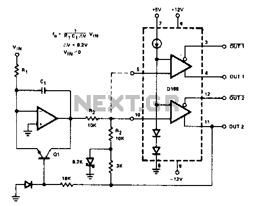
The D169 functions as a level detector, offering complementary outputs. An operational amplifier (op amp) is employed to integrate the input signal Vin, utilizing a time constant defined by the resistor R1 and capacitor C1. A negative input signal...
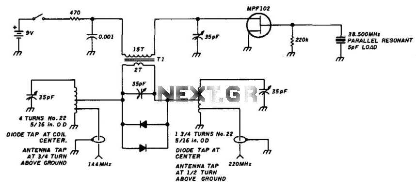
A simple circuit utilizing a single transistor converts 220 MHz to 144 MHz or vice versa, as the mixer is bilateral. The transformer has 15 turns on the primary and 2 turns on the secondary (#24 AWG wire) on...
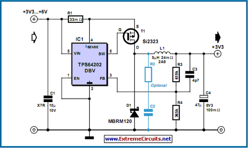
The TPS6420x controller is designed to operate from one to three series-connected cells or from a 3.3 V or 5 V supply obtained from a USB port. At its output, it can produce 3.3 V at 2 A, suitable...
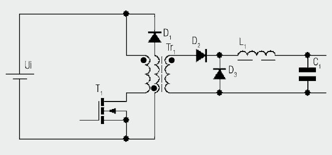
The diagram illustrates the basic construction of a forward converter. In contrast to the flyback converter, which temporarily stores energy before transferring it to the secondary side, the forward converter facilitates direct energy transfer between the primary and secondary...
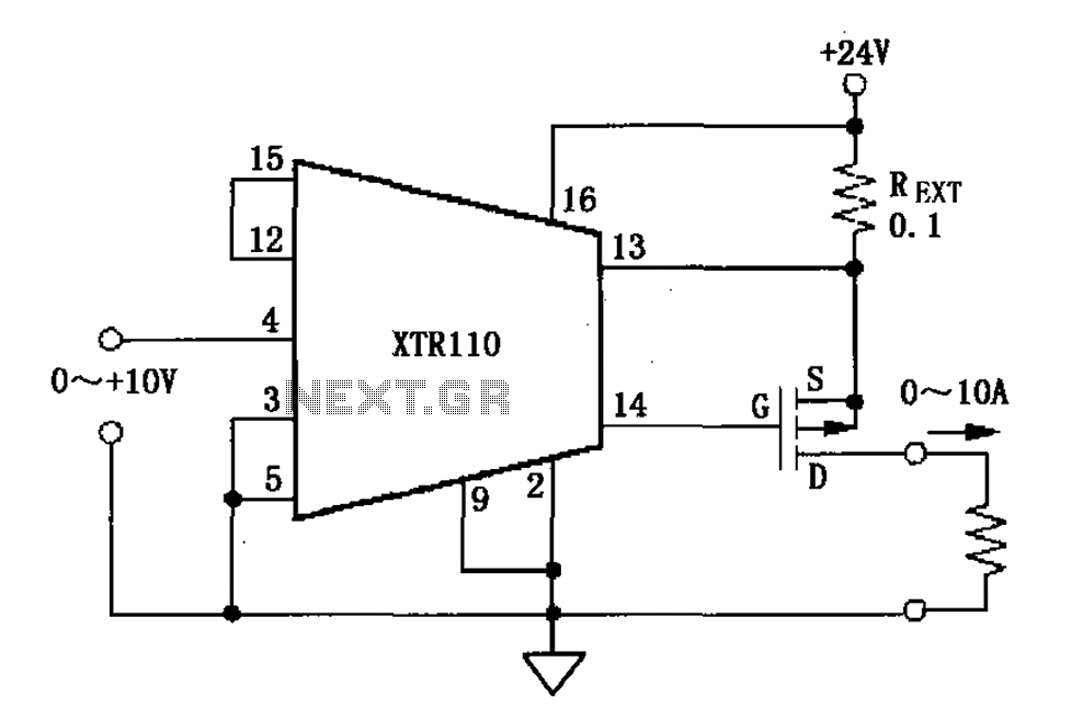
When the output current exceeds 40mA, the XTR110 requires the use of an external resistor (REXT) instead of the internal 50-ohm resistor (R9). REXT should be connected between pin 13 and pin 1. The value of REXT is determined...