
Model Glow Plag driver circuit

Rather than managing multiple energy sources, model builders typically prefer to use a single 12-volt battery. This battery can supply lower voltages through appropriate electronic step-down transformers (choppers). The pilot light benefits from negative feedback, maintaining a constant temperature during engine start-up, or while operating at different voltages.
In this circuit, a Programmable Unijunction Transistor (PUT) relaxation oscillator activates transistors Q1 and Q2, controlling the output of the chopper at a fixed repetition rate determined by resistors R and capacitor C1. Current flows through the spark plug and the parallel combination of resistor R2 and a current direction indicator associated with a Schmitt trigger. When the glow plug is cold (low resistance), current is high, which biases the Schmitt trigger "on," leading to Q3 providing base support for Q2. Once the glow plug reaches its operating temperature, controllable by its ohmic resistance, the Schmitt trigger is programmed to cut off the base drive to Q2 and Q3.
However, the glow plug's effectiveness depends on the voltage remaining constant, which is not always guaranteed. Transistor Q4 compensates for voltage drops (such as during a cold start) by increasing its collector current, which allows more current to flow through the diode, thereby delaying the cutoff point for the glow plug. This circuit maintains a relatively constant temperature, regardless of whether the glow plug is completely dry or wet, across an input voltage range from 8 to 16 volts. A similar configuration can be used to maintain a constant temperature for larger diesel truck glow plugs (28-volt supply, 12 volts). In this case, additional resistance may be necessary to manage temperature excursions due to hysteresis.
The circuit includes components such as Rc for compensation voltage trimming, Rp for temperature adjustment of the glow plug, and specific transistor models including 2N6028 and D29E2.model airplanes, boats, cars and use of ignition of glow plugs for their miniature (O. Bcc to 15cc) internal combustion engines. These engines happen with the heavy batteries on board, HT coil, and "condenser" spark required for ignition classic, while simultaneously developing much higher RPM (and thus power) as the compression ignition (diesel) engines . The heart of a candle is a coil of platinum alloy filament heated to start the engine by an external battery, or 1.
5 volts or 2 volts. To complete this battery, a second power supply of 12 volts is often necessary to start the engine, together with a third type 6 volt electric fuel pump. Rather than being overwhelmed by these multiple energy sources, the model builder prefer to wear (and buy) a single 12 volt battery, stemming from lower voltages from this by the use of appropriate electronic step-down transformers (choppers). The pilot light and shown it has the additional advantage of (through negative feedback) to maintain a constant temperature independent decision to drown the engine, or age volts while the starter is starting.
In this circuit, the PUT relaxation oscillator turns on transistor Ql Q2 output of the chopper at a fixed repetition rate determined by R and C1. The current then flows through the spark plug and the parallel combination of resistor R2 and the current direction indicator associated with the relaxation HILL Schmitt.
With the cold cap (low resistance), current is high, the hill is biased "on", and Q3 results in order to support the base of Q2. Once the cap has reached operating temperature, which can be controlled by its ohmic resistance, theHllL is programmed (via RJ extinguish, remove base drive of Q2 and Q3.
However, since the glow plug HAVL sense, no resistance, only val id if the voltage is constant, which is not always the case. Transistor Q4 provides adequate compensation in this case, if the voltage drops (during cold start, for example), the collector current of Q4 rises, causing more current through the diode, thereby delaying the cutoff point for a given socket.
The circuit has taken the temperature relatively constant, with the cap is completely dry or completely wet- 'on a range of input voltages from 8 to 16 volts. A similar configuration can be used to maintain a constant temperature of Plug size diesel truck full light (glow plug 28-volt supply, 12 volts), in this case, since the temperature excursions sheet is not so great resistance to expand HR hysteresis may be necessary ..
Rc - COMPENSATION VOLTAGE TRIM. Rp - TEMPEflATURE ADJUST PLUG. to - 2N6028 GENERAL ELECTRIC PCL - Hlll2. Q3 - D29E2 04.05-03301
Related Circuits
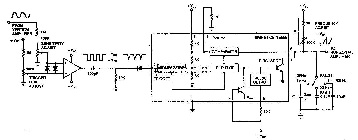
The circuit's input operational amplifier triggers the timer, sets its flip-flop, and cuts off its discharge transistor, allowing capacitor C to charge. When the voltage across the capacitor reaches the timer's control voltage of 0.33 Vee, the flip-flop resets,...
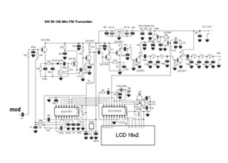
This is a straightforward high-quality PLL FM transmitter with a typical output power of 5 W and a no-tune design. It features RDS/SCA input and audio/MPX input with optional pre-emphasis and can operate with or without a stereo encoder....
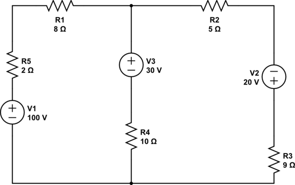
Using the superposition theorem, it is necessary to determine the current at all three nodes of the circuit. The current from the source, denoted as i_1, represents the current through V1 when other voltage sources are shorted out, in...
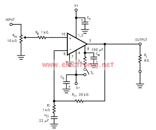
The LM3886 amplifier electronic circuit project is designed to deliver 68W of continuous average power into a 4-ohm load and 38W into an 8-ohm load with a total harmonic distortion plus noise (THD+N) of 0.1% across the frequency range...
The circuit operates similarly to the original strobes, but utilizes a glowing tube. The glowing tube remains constant, with the two electrodes continuously supplied with electricity. This current activates the two resistance components of the glow tube, causing mercury...
There have been several requests for a quiz circuit, leading to the development of a four-input design that can be easily modified. This design utilizes four integrated circuits (ICs) and features four input circuits, four independent outputs, and a...