
Design and Construction of Radio Frequency Oscillators

Radio frequency (RF) oscillators are essential components in various electronic systems, generating signals at specific frequencies used for communication, signal processing, and other applications. The design of RF oscillators involves several critical considerations, including frequency stability, phase noise, output power, and modulation capabilities.
The construction of RF oscillators typically involves selecting an appropriate oscillator topology, such as Colpitts, Hartley, or phase-locked loops (PLLs). Each topology has its advantages and is chosen based on the specific application requirements. Components such as inductors, capacitors, and active devices (transistors or operational amplifiers) are carefully selected to achieve the desired frequency of oscillation and to ensure stability against variations in temperature and supply voltage.
In addition to the basic circuit design, RF oscillators often require careful layout techniques to minimize parasitic effects and electromagnetic interference (EMI). This includes the use of ground planes, shielding, and proper routing of RF traces to maintain signal integrity. The use of simulation tools can aid in predicting the performance of the oscillator before physical construction, allowing for optimization of component values and layout.
Testing and validation of RF oscillators involve measuring key parameters such as output frequency, power levels, and phase noise using specialized RF test equipment. This ensures that the oscillator meets the required specifications for its intended application, whether it be in telecommunications, broadcasting, or other RF applications.the RF design and construction of radio frequency oscillators. 🔗 External reference
Related Circuits
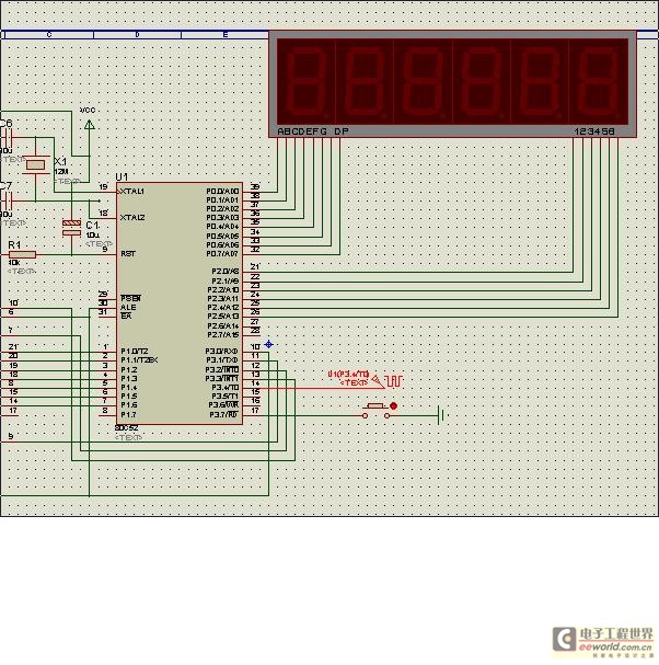
This design synthesis considers the accuracy of frequency measurement and the requirements for response time. For instance, when measuring a frequency of 1 Hz, the measurement duration must exceed 1,000 seconds to accurately count the gate width. To ensure...
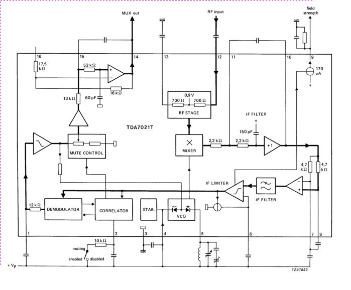
The TDA7021T integrated radio receiver circuit is designed for portable radios, both stereo and mono, where minimal peripheral components are essential for achieving small dimensions and low cost. It is fully compatible. The TDA7021T is a highly integrated radio receiver...
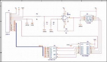
This example demonstrates the design of a circuit that incorporates both analog and digital components, features multiple power planes, and utilizes a single ground plane that is divided into analog and digital sections while maintaining a common reference point. The...
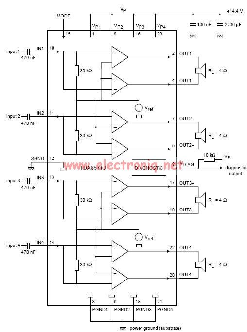
This electronic circuit diagram represents an audio power amplifier utilizing the TDA8571J integrated circuit. It is a class-B output amplifier configured in a BTL (Bridge-Tied Load) arrangement, featuring four amplifiers, each with a gain of 34 dB. The main...
Information about building a small radio transmitter, which has a PCB measuring 1.75" x 2.5" (45mm x 68mm) and has a range of approximately 30 yards. The documentation states that the frequency range is 100-108 MHz, but it has...
This sound frequency meter circuit is simple to build and can be constructed in a portable format. It can measure frequencies with a minimum level of 10 mV. The sound frequency meter circuit is designed to provide an effective and...