
220Mhz Receiving Converter

The described circuit serves as a frequency converter, capable of shifting signals between 220 MHz and 144 MHz, which can be particularly useful in radio frequency applications. The core component of this circuit is a single transistor that functions as a mixer, allowing for bidirectional signal conversion due to its bilateral nature.
The transformer used in this circuit is critical for the conversion process. It consists of a primary winding with 15 turns and a secondary winding with 2 turns, both wound with #24 AWG wire. The choice of wire gauge and the number of turns are essential for achieving the desired impedance transformation and frequency response characteristics. The use of a toroidal core made from SF material (Silicon Ferrite) provides a compact and efficient magnetic structure that minimizes losses and enhances performance at high frequencies.
In terms of operation, the circuit can accept an input signal at one frequency and produce an output signal at the other frequency. This is achieved by mixing the input signal with a local oscillator signal within the transistor, generating the desired frequency output. The design's simplicity allows for ease of implementation, while the careful selection of components ensures reliable operation across the specified frequency range.
Overall, this circuit exemplifies a straightforward yet effective approach to frequency conversion in RF applications, demonstrating the utility of basic electronic components in achieving complex signal processing tasks. A simple circuit using a single transistor converts 220 MHz to 144 MHz or vice versa, because the mixer is bila teral. Tl has 15 turns on the primary, and 2 turns on the secondary (#24 AWG wire) on a 0.375" ID SF-material toroidal coil.
Related Circuits
When the power supply is connected to IC1, the output pin 3 operates at a frequency of 1 kHz. The components Q1 and Q2 work in a push-pull configuration. When a positive output signal is generated, Q1 and Q2...
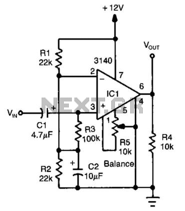
An operational amplifier (op amp) configured as a comparator generates a 10-V peak-to-peak square wave output with a 100-mV input signal, operating up to 15 kHz. Adjust resistor R5 to achieve symmetry in the square wave at low input...
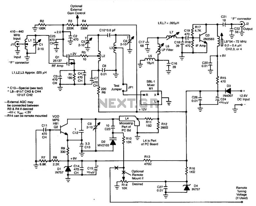
Ll, Ql, L2, and L3 form an RF amplifier stage that feeds Ml, a doubly balanced mixer. Q4 is a local oscillator stage operating in the 375-MHz range. Signals in the 420- to 450-MHz range from Ql are mixed...
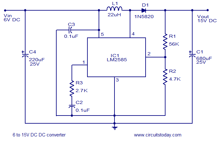
A simple and efficient 6 to 15V boost/step-up DC to DC converter based on IC L2585. This voltage converter circuit requires few external components. The circuit utilizes the L2585 integrated circuit, which is designed for high-efficiency voltage boosting applications. The...

This circuit features a PMOS enhancement-mode FET input buffer amplifier connected to a traditional absolute value circuit, which effectively mitigates the impact of the forward voltage drop across diodes D1 and D2. The described circuit employs a PMOS enhancement-mode field-effect...
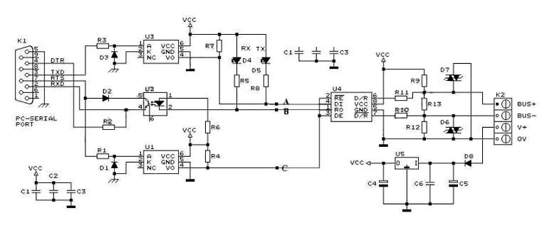
RS232 to RS485 Converter Circuit Schematic. RS232 to RS485 converters are primarily utilized in industrial and commercial settings. The RS232 to RS485 converter circuit is designed to facilitate communication between devices using different serial communication standards. RS232 is commonly found...