
Low Power FM Transmitter

This low power FM transmitter circuit is a practical solution for audio transmission applications, particularly in settings where minimal power consumption is desired. The oscillator stage, based on a Colpitts configuration, utilizes Q1 to achieve frequency modulation. The modulation process is initiated by an audio signal that influences the base of the transistor, thereby altering its collector current and affecting the oscillation frequency. This design allows for effective transmission of audio signals over the FM band, making it compatible with standard FM receivers.
The tuning process is facilitated by the variable capacitor C3, which must be adjusted to find an unused frequency. The connection of C3 to a +9V power supply is critical, as it stabilizes the circuit and prevents unwanted frequency shifts when making adjustments. The use of a non-copper-clad screwdriver is a practical consideration, as it avoids introducing additional capacitance that could disrupt tuning.
The inductors, constructed from 1mm diameter enameled copper wire, are wound around a 3mm diameter former. This construction method ensures that the inductance is optimized for the desired frequency range. After winding, the former is removed to leave behind coils that are essential for the oscillator's functioning.
The output power of 100 mW is sufficient for localized broadcasting, allowing users to transmit audio signals effectively within a limited range, such as a neighborhood or community. With the right antenna, the transmitter's range can be extended, making it a versatile option for various audio transmission needs. For applications requiring higher transmission power, a selection of transmitters is available, catering to different power requirements.This low power fm transmitter is designed to use an input from another sound source and transmits on the commercial FM band. This low power fm radio transmitter it is actually quite powerful The first stage is the oscillator, and is tuned with the variable capacitor.
Select an unused frequency, and carefully adjust C3 until the background noise stops (you have to disable the FM receiver`s mute circuit to hear this). When assembling the fm transmitter circuit, make sure the rotor of C3 is connected to the +9V supply. This ensures that there will be minimal frequency disturbance when the screwdriver touches the adjustment shaft.
You can use a small piece of non copper-clad circuit board to make a screwdriver this will not alter the frequency. Q1 is a conventional Colpitts oscillator design. The audio signal applied to the base of Q1 causes the frequency to change, as the transistor`s collector current is modulated by the audio.
This provides the frequency modulation (FM) that can be received on any standard FM band receiver. The inductors are 9. 5 turns of 1mm diameter enamelled copper wire. They are close wound on a 3mm diameter former, which is removed after the coils are wound. The output is a low power of 100 mW, but for some of you this fm rf transmitter can delivers the desired power for broadcasting on your street or with a proper antenna you can cover a small neighborhood. If you need a power wireless fm transmitter use the above menu, you can find transmitters starting with low fm power up to high power fm transmitters.
🔗 External reference
Related Circuits
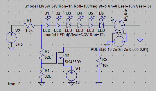
A suitable method to sense when some LEDs in a garage door opener are illuminated. A power source, potentially the same as Vout, connects to a 1.5 kΩ resistor, which then connects to six LEDs followed by a transistor....
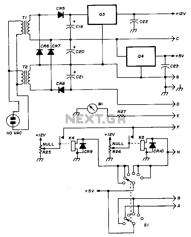
The Hewlett-Packard HSCH-3486 zero-bias Schottky diode is utilized as the detector. To avoid employing a modulation detection method, a chopper-stabilized operational amplifier is implemented. The chopper operational amplifier effectively converts the input DC voltage to AC, amplifies it, and...
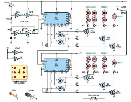
This simple dual digital dice is based on three low-cost integrated circuits (ICs), a few transistors, and several light-emitting diodes (LEDs). IC1a and IC1b function as oscillators with a specific frequency. The dual digital dice circuit utilizes three low-cost integrated...
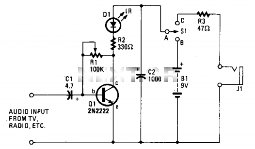
The ultra-simple one-transistor IR transmitter is designed to transmit sound from any 8 or 16-ohm audio source, such as a TV, radio, or tape recorder, using an infrared beam of light. The one-transistor infrared (IR) transmitter circuit operates by modulating...
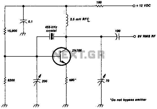
This crystal-oscillator circuit utilizes a 455-kHz crystal. It is a straightforward project. The crystal oscillator circuit based on a 455-kHz crystal operates by utilizing the piezoelectric properties of the crystal to generate a stable frequency. The circuit typically consists of...

An FM and AM transmitter integrated into a compact device utilizing the CD4001 integrated circuit. It broadcasts at 20 MHz for AM and 100 MHz for FM. The described transmitter combines both Frequency Modulation (FM) and Amplitude Modulation (AM) capabilities...