
switch mode power supply design of current load sense circuit

The circuit design involves a series of interconnected components that work together to achieve the desired LED dimming and external light control functionality. The initial stage includes a power source connected to a resistor, which limits the current flowing through the LEDs. The six LEDs are arranged in a configuration that allows their brightness to be controlled via the PWM signal generated by the PIC18F4520 microcontroller. This microcontroller's pin 7 is crucial for modulating the signal, which is necessary for achieving the dimming effect on the LEDs.
The transistor acts as a switch, controlling the current flow to the LEDs based on the PWM signal. The choice of a suitable transistor is essential to ensure that it can handle the current required by the LEDs without overheating or failing. The grounding of the transistor is a critical design choice, as it allows the microcontroller to effectively control the operation of the LEDs.
The integration of the external 12V LED strip introduces another layer of complexity. The intention to use a buck converter to step down the voltage from the opener's Vout to power the LED strip is a practical solution, but it necessitates careful consideration of the converter's efficiency and load characteristics. The use of a voltage divider to supply the MOSFET adds another level of control, allowing for the external light to be turned on or off in response to the PWM signal.
Concerns about the stability of Vout are valid, as fluctuations could impact the performance of both the LED dimming and the external light control. Testing the circuit under various load conditions will be critical to understanding how these variables affect the overall functionality. The desire to utilize the SHDN pin for power management during inactive periods is a forward-thinking approach, aimed at enhancing energy efficiency, though it may require further circuit modifications to implement effectively.
Overall, this circuit design presents a robust method for controlling LED lighting within a garage door opener system while also enabling the operation of an external light source. Careful attention to component selection, circuit stability, and power management will be essential for achieving the desired performance outcomes.A suitable method to sense when some LEDs in my Garage Door Opener are on. A power source (perhaps the same as Vout below) runs to a 1. 5Kohm resistor which runs to 6 LEDs then a transistor of some sort. The transistor is attached to ground and pin 7 on a PIC18F4520. Pin 7 on the PIC is a digital out thus I`m assuming PWM is used to dim the LEDs. To use the Opener as a control signal to control an external light repeating the PWM for fancy dimming. The external light is a 12V 1W LED strip. Power for the external light I was hoping to also take from the Opener`s Vout using a buck converter. Existing parts in the Opener: V2 = Vout and/or the LED power source (not sure if they`re one and the same) R1 is the current limiting resistor D1-6 are the existing LEDs Additional components for my circuit are: R3, R4 voltage divider to power the mosfet.
M1 FQP27P06 mosfet, I`ve chosen another mosfet in ltspice which should be similar. V1 12v out from the D24V3AHV buck converter. R5 simulated load for testing in ltspice. This will be replaced with the external light. What I`m not showing here is the power coming into the buck converter. This will come from Vout and Gnd. My primary concern here is that my output will be all whack because Vout is not a constant voltage source it seems. That and I will be modulating the load on the buck converter meaning it`s voltage might go all over the shop.
There doesn`t seem to be any data available from Pololu on the exact behaviour. The buck converter is > 80% efficient when Vin is 24v and driving 12v @ 48mA for the LEDs. Given 24v @ 55mA is 1. 32W I calculate that I can safely draw 80% of this which is 1. 056W. Not much room for error however I haven`t yet received the parts I will be using for this so I haven`t tested how the regulator is affected by changes in voltage supply or loading. The info on the site hasn`t been much help. I`m wondering if there`s a better way of doing this I`m probably causing myself headaches by trying to pull a signal from these four connection points.
The problem is that nearly everything is SMD and I`m not confident enough with an iron to wire into the PIC pin or anything there. Also, I was wondering if there would be a way to also use the SHDN pin on the buck converter to draw less power when the system is inactive.
With my current draft I can`t see it being possible. 🔗 External reference
Related Circuits
This audio processor circuit features the SSM2045 integrated circuit (IC), designed specifically for electronic music applications, along with the 741 operational amplifier (op-amp) IC. The circuit is configured as a low-pass filter with a DC voltage control for gain....

The reading lamp consists of a small solar panel, a standard UPS style lead acid battery, and an LED circuit board. The circuit board contains a low power solar charge controller (regulator), a set of 8 white LEDs, a...
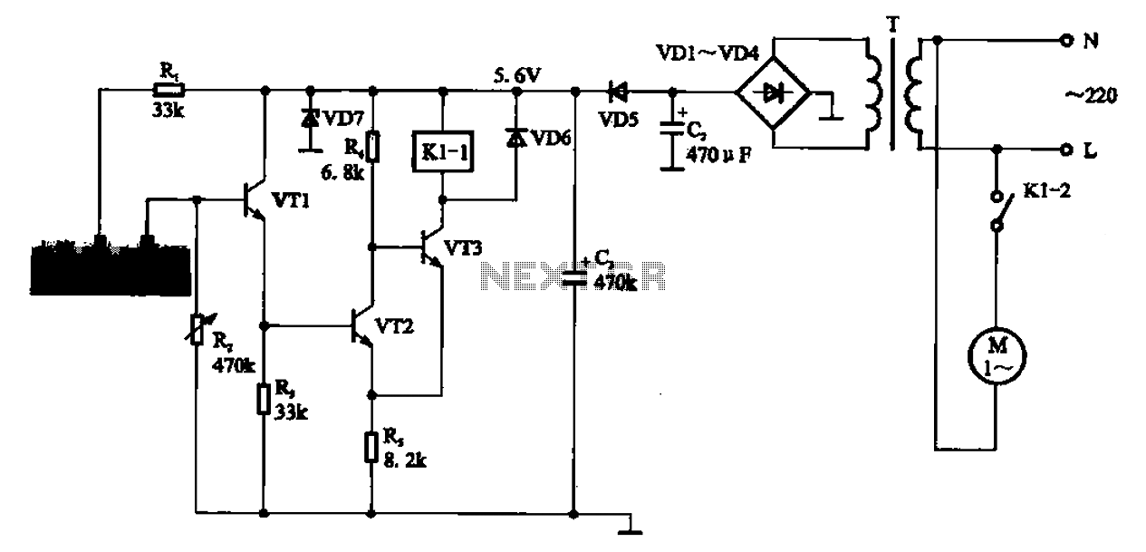
AC motor control circuit for a sprinkler. If the circuit involves an AC motor, it can be designed according to the connection shown in the figure, detailing the work process and the underlying principles of the circuit. The AC motor...

When the touch switch SI is activated, resistor R4 is driven high, causing the control voltage to rise, which latches the switch. Conversely, when switch S2 is activated, resistor R4 goes low, resulting in a decrease in the control...
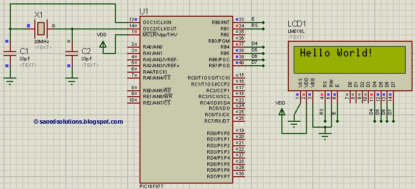
This tutorial on the PIC16F877 microcontroller addresses the question, "How to interface an LCD in 4-bit mode with the PIC16F877?" It also utilizes the PIC16 simulator (Proteus). The PIC16F877 microcontroller is a versatile device widely used in embedded systems. This...
This document explains a simple circuit designed to remotely switch on or off any electrical device using a relay, controlled by a standard TV or VCR. The circuit utilizes a relay as the primary switching element, enabling the control of...