
Low-Cost Dual Digital Dice

The dual digital dice circuit utilizes three low-cost integrated circuits to create a simple yet effective random number generator. The primary components include two oscillators (IC1a and IC1b), which generate clock pulses at a defined frequency. These oscillators are typically configured using a 555 timer IC or similar, producing a square wave output that drives the subsequent logic in the circuit.
Transistors are employed to amplify signals and control the operation of the LEDs, which visually represent the dice rolls. The LEDs are arranged in a manner that allows them to light up in patterns corresponding to the numbers displayed on traditional dice. The circuit can be designed to show numbers from one to six for each die, with the output being triggered by a push-button switch or a similar input mechanism.
The circuit's operation begins when the user activates the switch, causing the oscillators to start generating clock pulses. These pulses are fed into a binary counter or a similar digital logic component, which counts the pulses and determines the output state. As the counter increments, it activates the appropriate LEDs to reflect the current count, simulating the roll of two dice.
To enhance the user experience, additional features can be integrated, such as sound effects using a small speaker or buzzer that activates with each roll, or a reset function that allows the user to clear the displayed numbers. The design can be compact, making it suitable for portable applications or as a fun addition to board games. Overall, this dual digital dice circuit combines simplicity and functionality, making it an excellent project for electronics enthusiasts.This simple dual digital dice is based on three low-cost ICs, a few transistors and a handful of LEDs. IC1a & IC1b operate as an oscillator with a frequen.. 🔗 External reference
Related Circuits

When the upper or lower limit is exceeded, the LED lights up. Positive feedback to one of the nulling terminals creates 5 to 20 pV of hysteresis on both amplifiers. This feedback changes the offset voltage of the LT1002...
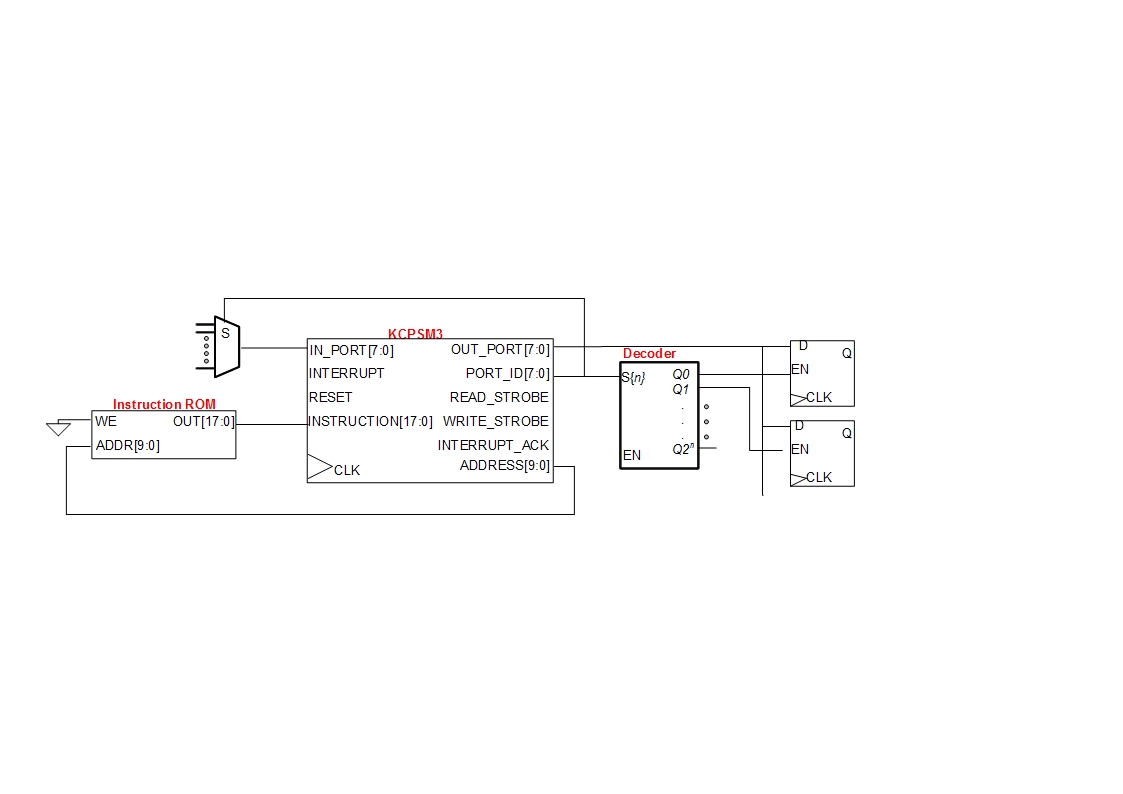
A small digital design utilizes a Xilinx Picoblaze softcore processor. Creating acceptable quality schematics has proven to be frustrating and time-consuming. Previous attempts to integrate existing schematics from LTSpice or Eagle into the documentation yielded unsatisfactory results, appearing fuzzy...

Used for digital control of musical instruments, this transmitter converts digital data signals into equivalent optical signals for a fiber optic cable interface. Optocoupler IC1 provides isolation, driving IC2-a and -b, and T1, ultimately providing a cable driver LED...
This circuit provides a straightforward and efficient method for interfacing two relays in switching applications. The relay driver utilizes a standard BC547 NPN transistor (or equivalent) to enhance the input impedance. It is a widely used driver capable of...
This is a slightly revised version of the 6-transistor H-bridge designed by Mark Tilden and found on the BEAM Tek website (now only available via archive). I encourage anyone interested in H-bridges to read Mark's article, as it gives...

A diode (IN4148) is utilized as a temperature sensor. IC2 is an A/D converter with BCD output. A reference voltage set by R7 is applied to the positive input of IC2. As the temperature rises, the voltage across the...