
Low Power LED Battery Voltmeter

The voltmeter circuit is particularly advantageous for renewable energy applications, where monitoring battery voltage is crucial for system efficiency and longevity. The use of the LM3914N IC allows for precise voltage readings, while the low power consumption ensures minimal drain on the battery, extending operational life. The flexibility in LED selection not only enhances visibility but also allows for aesthetic customization of the device. The careful design considerations, such as the inclusion of a fuse for safety and the ability to switch between power modes, underline the circuit's reliability and user-friendliness. This voltmeter circuit exemplifies an efficient solution for voltage monitoring in alternative energy systems, combining functionality with ease of use.This is a low power voltmeter circuit that can be used with alternative energy systems that run on 12 and 24 volt batteries. The voltmeter is an expanded scale type that indicates small voltage steps over the 10 to 16 volt range for 12 volt batteries and over the 22 to 32 volt range for 24 volt batteries.
Power consumption can be as low as 14mw wh en operated from 12V and 160mw when operated from 24V. It is possible to set the meter to read equal steps across a variety of upper and lower voltages. The meter saves power by operating in a low duty-cycle blinking mode where the LED indicators are only on and consuming power briefly during a repeating 2 second cycle. The circuit may be switched to a high power mode where the active LED stays on at all times. Different colored LEDs may be used for the voltage level indicators, this allows the battery state to be read in the dark.
With the new blue LEDs, it is possible to have a nice looking rainbow of colors using two each of red, amber, yellow, green, and blue LEDs. The circuit will also work with inexpensive and common red LEDs. If the circuit is to be used in sunlight, ultra-bright LEDs should be used, although even those may be hard to read without some kind of sun shield.
The heart of the circuit is the LM3914N dot-bar volt meter IC, U2. This chip is operated in the expanded-scale mode so that the circuit responds in the 10-16V range. U2 outputs a steady voltage on pin 7 from the internal voltage reference. This is fed via voltage dividers VR2 and R5 to the internal reference input pins to set the range that the meter is sensitive to. The measured voltage is fed in on pin 5 via the voltage divider consisting of R4 and VR1. This divider scales the input voltage down to a range that is useful to the IC. The U2 positive supply is connected to pin 3 which is nominally 12V. The U2 negative supply is switched on momentarily via transistor Q1, this switching action is what makes the circuit efficient since U1 (ICM7555) consumes a mere 0.
34 ma while U2 consumes around 18ma with one LED on. The ICM7555 timer, U1 is wired to run in a free-running mode with a narrow pulse width square wave output. The duty-cycle of U1 is controlled by the ratio of R1 and R2. R2 may be adjusted to a smaller value if faster blinking is desire, a potentiometer may be substituted for R2 if a rate adjustment is desired.
R1 may be increased if a longer on-time is desired. Changes in R1 and R2 will affect the average current that the circuit consumes. The frequency of oscillation is determined by C1, R1, and R2. C1 may be either an electrolytic or poly capacitor, if an electrolytic part is used, be sure to connect the positive terminal to U1 pins 6 and 2 and the negative terminal to ground. The output of the timer IC is fed through current limiting resistor R3 to transistor Q1 which controls power to U2.
Capacitor C2 filters the control voltage input to U1 and capacitor C3 provides DC filtering for the whole circuit. When the lock-on switch across capacitor C1 is closed, the output of the timer remains on, thus enabling the U2 circuitry and increasing the current drain to 18ma.
The reason the switch is not simply wired across the transistor is to keep the negative supply to U2 the same as when the circuit is pulsed on. This maintains the same calibration on the LEDs in both modes because the transistor`s voltage drop is always part of the circuit.
Last, but not least, fuse F1 protects against the potential for fire hazard should the circuit become shorted out. The average current is calculated by adding the constant current required by U1 with the product of the current from U2 times the duty cycle, see the specifications for details.
To operate the circuit in the 12V mode, wire the circuit so that jumpers J2 and J5 are shorted, parts U3, C4, R6, and R7 may be left out. When wired for 24 Volt operations, the meter responds in the 20-32V range. R6 i 🔗 External reference
Related Circuits
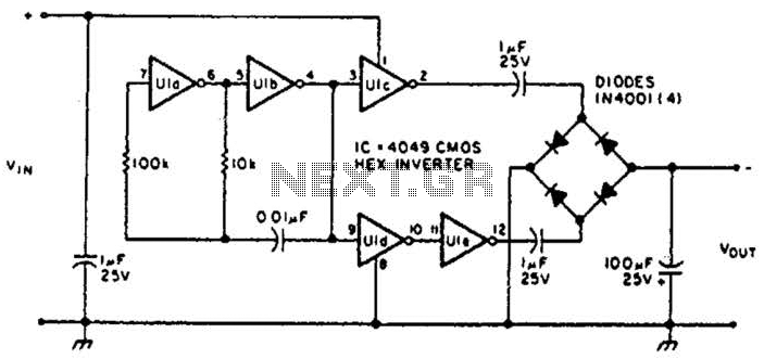
This circuit will provide a negative DC voltage that is approximately equal to the positive input voltage at no load and about 3 V less at a 10 mA load. The input voltage range is from +5 to +15...
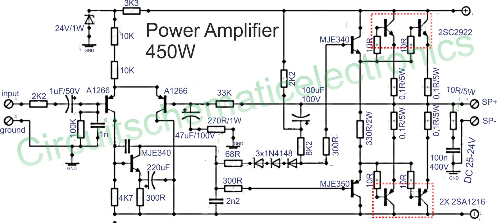
Below is a circuit of power amplifiers with a power output of 450 watts in mono mode. These amplifiers are frequently utilized in high-power applications, suitable for events, and designed for enclosed spaces. This amplifier is appropriate for woofers...
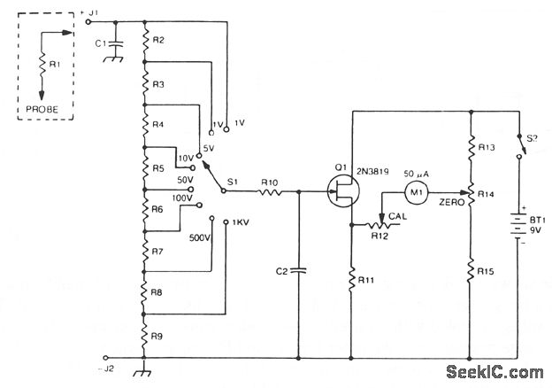
The 2N3819 FET serves as a solid-state voltage output meter (VOM). In this configuration, the 2N3819 functions as a cathode follower. The bias offset, or meter null, is achieved using resistors R14 and R12, while the full-scale calibration is...
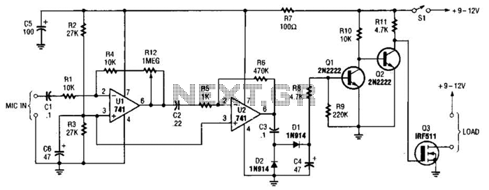
This audio-controlled switch integrates a pair of 741 operational amplifiers, two 2N2222 general-purpose transistors, an hcxFET, and several supporting components into a circuit capable of activating devices such as a tape recorder, a transmitter, or virtually any sound-activated equipment. The...
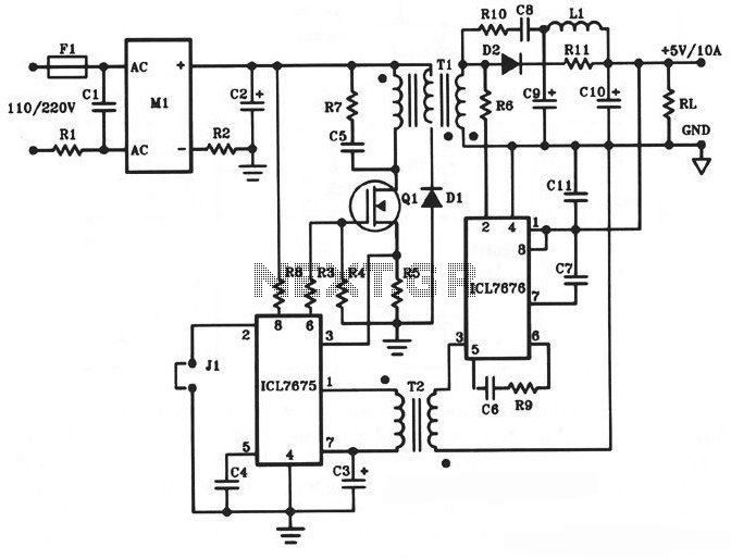
The following diagram illustrates a 50W offline switching power supply circuit design. This circuit is powered by a MOSFET, specifically the BUZ80A/IXTP4N8 for a 220V AC voltage input and the GE IRF823 for a 110V AC voltage input. The...
This architecture allows for a wide tolerance in component selection, enabling the use of various components that may be readily available. The transistors utilized can be any NPN type power transistor, excluding Darlington configurations. The output power is approximately...