
low power switching regulator

The described circuit functions as a step-down (buck) converter, converting a higher voltage (9V) to a lower regulated output voltage (5V). The key components include a transistor (Q1), which acts as a switch, an inductor, a feedback operational amplifier (A1), and a capacitor for filtering.
In the operational phase, when Q1 is activated, current flows through the inductor, storing energy in its magnetic field. The feedback mechanism involving A1 monitors the output voltage. As the output voltage approaches the desired level, A1 adjusts the base drive of Q1 to maintain regulation. When the output voltage exceeds the set point, A1 reduces the drive to Q1, causing it to turn off and subsequently allowing the inductor to discharge through the output load, thereby providing continuous power.
The inclusion of the 1 µF capacitor plays a crucial role in maintaining stability and performance by providing a low-impedance path for high-frequency components of the load current. This capacitor helps to mitigate voltage dips during rapid load changes or switching events, ensuring that the output voltage remains stable and within specified limits.
Overall, this circuit exemplifies a compact and efficient solution for voltage regulation in battery-operated devices, achieving a balance between power efficiency and output stability. The design can be further enhanced by selecting components with appropriate ratings and characteristics to optimize performance for specific applications.This circuit is a simple battery-powered switching regulator provides 5V out from a 9V source with 80% efficiency and 50-mA output capability. When Q1 is oon, its collector voltage rises, forcing current trhough the iinductor. The output voltage rises, causing A1`s output to rise. Q1 cutts off and the output drops low enough for A1 to turn Q1. The 1 uF capacitor ensures low battery impedance at high frequencies, preventing sag during switching. See schematic diagram below : 🔗 External reference
Related Circuits
This low voltage circuit can be used to monitor batteries and other volatile sources of current for problems. The circuit sounds an alarm and lights an LED, but can be interfaced to any number of other circuits for many...
What is the purpose of this circuit? Basically it has two roles: to pass the desired low frequency signals and stop the unwanted high frequency signals. Open the netlist file lpfilter1.cir with your SPICE simulator. Most simulators display the...
This chapter presents detailed schematics for various power supplies compatible with commonly available Ar/Kr ion tubes in the surplus market. It includes examples of commercial designs such as the Omnichrome 150R and 532 head, Lexel 88 and head, alongside...
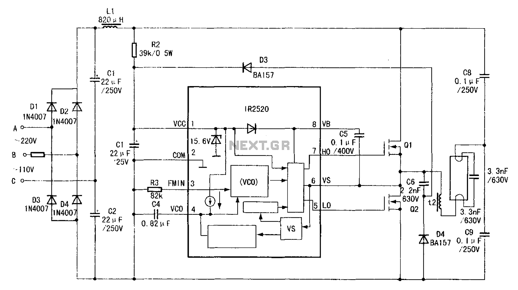
The adaptive zero voltage switching electronic ballast schematic diagram utilizes the IR2520 primarily for driving fluorescent lamps of 40W or less. The parameters of components such as Q1, Q2, L2, and C7 vary depending on the rated power of...
Using this circuit you can convert the 12V dc into the 220V AC. In this circuit, 4047 is used to generate the square wave of 50Hz and amplify the current and then amplify the voltage by using the step...
This is a variable power supply controlled by a PIC microcontroller. An LCD display is included in the circuit to show the actual output voltage and current values. A push-button switch is used to adjust the output voltage and...