
Low Voltage Alarm

The low voltage monitoring circuit is designed to provide real-time feedback on the status of batteries and other current sources, ensuring that any irregularities in voltage levels are detected promptly. The circuit typically consists of a voltage divider, a comparator, an LED indicator, and a sound alarm, which can be integrated into a broader system.
The voltage divider is formed by two resistors connected in series across the battery or current source. This configuration reduces the voltage to a manageable level for the comparator, which is the heart of the monitoring system. The comparator is set to a reference voltage that corresponds to the acceptable range for the battery voltage. When the voltage from the battery falls below this threshold, the comparator output changes state.
The output of the comparator is connected to a transistor, which acts as a switch. When the comparator detects a low voltage condition, it turns on the transistor, allowing current to flow through the LED and the alarm circuit. The LED illuminates to provide a visual indication of the problem, while the alarm sounds to alert users to the issue.
Additionally, the circuit can be designed to interface with other systems. For instance, it can send a signal to a microcontroller or a more complex alarm system for further processing or logging of the event. This flexibility allows the circuit to be customized for various applications, including battery management systems, power supply monitoring, and other safety-critical environments.
Overall, this low voltage monitoring circuit is a versatile and essential tool for ensuring the reliability and safety of battery-operated devices and other electronic systems.This low voltage circuit can be used to monitor batteries and other volatile sources of current for problems. The circuit sounds an alarm and lights an LED, but can be interfaced to any number of other circuits for many different uses.
🔗 External reference
Related Circuits
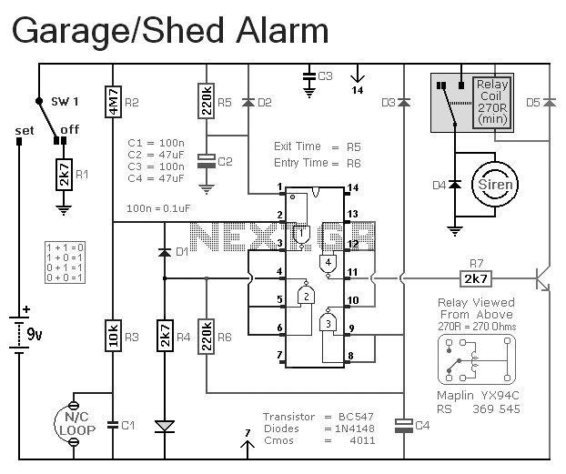
This is a simple single-zone burglar alarm circuit. Its features include automatic exit and entry delays. It is designed to be used with the usual types of normally-closed input devices such as magnetic reed contacts, micro switches, foil tape,...
In this circuit, the alarm is activated under four different conditions: 1. When light falls on LDR1 (located at the entry to the premises). 2. When light falling on LDR2 is obstructed. 3. When door switches are opened or...
The lf555afosc1.pdf file download contains a diagram with annotations for a Sub-Tone (CTCSS or "PL") Oscillator, designed using the well-known 555 timer IC configured for astable multivibrator operation. The component values are selected to position the tone range near...
Commonly used 3-pin linear voltage regulators, such as the LM317, cannot handle input voltages exceeding approximately 30V. The LR8A from Supertex Inc is a new adjustable three-pin regulator capable of accepting input voltages up to 450V and supplying an...
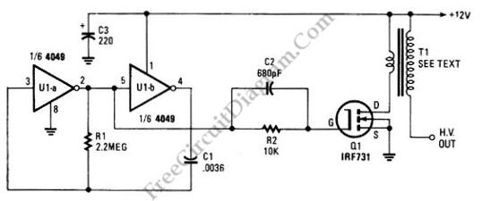
The schematic diagram below illustrates a high voltage generator circuit. This circuit employs a 4049 hex inverter functioning as an oscillator, with the option to utilize an ignition transformer from an automotive engine. A flyback transformer may also be...
This circuit can generate a voltage of 15V. In this circuit, the LM340 input voltage must remain within the limits specified in the data sheet. If the device is operated above the absolute maximum input voltage rating, two failure...