
Low Power Voltage Doubler Booster
The described voltage doubler circuit is particularly advantageous for applications in portable electronic devices where space and power efficiency are critical. The use of an astable multivibrator (IC1) to generate the necessary pulse signals is a common practice in power supply design, as it allows for precise control over the output voltage and current characteristics. The selection of transistors T1 and T2 plays a significant role in the circuit’s performance; they must be chosen based on their switching speed and current handling capabilities to ensure optimal operation.
Diodes D1, D2, and D3 are essential in directing the flow of current and preventing reverse voltage that could damage the components. Capacitor C4 acts as an intermediary storage component, allowing for the charge to be built up before transferring to C5, which serves as the output capacitor. The design ensures that the charging and discharging processes are synchronized with the pulse generation, maximizing efficiency.
For optimal performance, the circuit layout should minimize parasitic capacitance and inductance, which can adversely affect the high-frequency operation of the astable multivibrator. Additionally, careful consideration should be given to the physical placement of components on the PCB to reduce noise and enhance stability.
In summary, this low-power voltage doubler circuit represents an effective solution for applications requiring higher voltage from limited power sources, maintaining both efficiency and compactness in design.All miniature electronic devices operate off batteries. Some of them need higher than the standard battery voltages to operate efficiently. If the battery of that specific voltage is unavailable, we are forced to connect additional cells in series to step up the DC voltage. Thus, the true meaning of miniaturisation is lost. A simple way to overcom e this problem is to employ a voltage doubler, if the device under consideration can operate at a small current. Here we present a low-power voltage doubler circuit that can be readily used with devices that demand higher voltage than that of a standard battery but low operating current to work with.
The circuit is quite simple as it uses only a few components. Yet, the output efficiency is 75 to 85 percent along its operating voltage range. The available battery voltage is almost doubled at the output of the circuit. Here IC1 is wired as an astable multivibrator to generate rectangular pulses at around 10 kHz. This frequency and duty cycle of the pulses can be varied using preset VR1. The pulses are applied to switching transistors T1 and T2 for driving the output section, which is configured as a voltage-doubling circuit. The doubled voltage is available across capacitor C5. During each cycle of the pulse occurance, the high level drives T1 into its saturation, keeping transistor T2 cut off.
So transistor T1 charges capacitor C4 via the path formed by diodes D2 and D1 to a voltage level slightly lesser than the supply. But during the low period of the pulse, transistor T1 is cut off while transistor T2 is driven into saturation.
Now, transistor T2 raises the charge on the negative pole of capacitor C4 by another step equal to the supply voltage. Therefore an equal amount of charging is built up on capacitor C5 via diode D3. This doubling action increases the total voltage across capacitor C5 to almost double the input voltage.
If the output of the pulse generator is maintained with a high enough amplitude and frequency, the output voltage and current remain constant and cater to the needs of the load. Even with the half-wave function, this circuit is almost free of ripple voltage. If the connected load doesn`t require a high current, the efficiency can be expected in the upper 90 percentranges.
Since the input voltage is doubled, the current drain from the input power supply is also doubled at the input but halved at the output. One point of caution is that if the multivibrator`s frequency is fairly high, the output may suffer with the interference imposed over the DC voltage.
In this case, the frequency must be set favorably by trials and actual load connection procedure. This tiny circuit can be assembled on the general-purpose PCB. If all of the components are surface-mount type, the whole module can be genuinely miniaturized. 🔗 External reference
Related Circuits
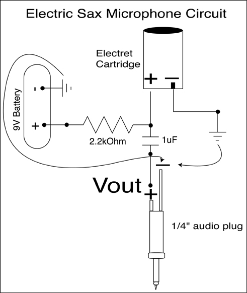
A condenser microphone (electret type with two terminals) is to be powered. A resistor of 1 kΩ and a capacitor of 10 µF have been connected to its positive terminal, while the other terminal is grounded. To power an electret...
The National Semiconductor LMV225 is a linear RF power meter integrated circuit (IC) housed in a surface-mount device (SMD) package. It operates within a frequency range of 450 MHz to 2000 MHz and requires only four external components for...
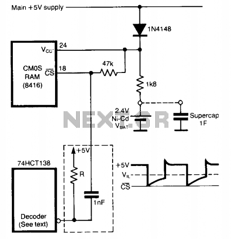
To prevent data loss when a CMOS RAM transitions from normal operation (Vcc = 5 volts) to standby mode (Vcc = VBAT), it is crucial to maintain the CS pin close to the Vcc rail at all times. This...
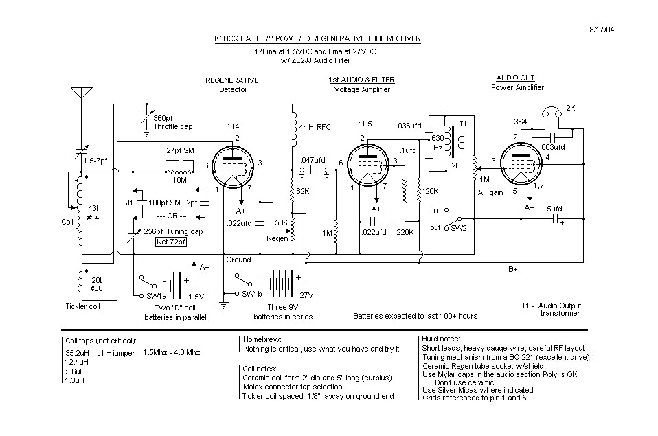
The basic regenerative design is quite common. Before the schematic is created, there is a "concept stage," followed by the "available components stage," returning to the "concept stage," then moving on to the "mechanical/electrical layout stage," and finally sketching...

Another method of using opamps to regulate a power supply is shown below. The power transformer requires an additional winding to supply the op-amps with a bipolar voltage (+/- 8 volts), and the negative voltage is also used to...
The 2SK2975 has reportedly been discontinued by the manufacturer, with the RD07MVS1 from Mitsubishi serving as its replacement. This new device is very similar but appears to have slightly higher gain—10 dB typical at 520 MHz compared to 8.4...
Warning: include(partials/cookie-banner.php): Failed to open stream: Permission denied in /var/www/html/nextgr/view-circuit.php on line 713
Warning: include(): Failed opening 'partials/cookie-banner.php' for inclusion (include_path='.:/usr/share/php') in /var/www/html/nextgr/view-circuit.php on line 713