
Low Supply Rail Detection

The low supply rail detection circuit operates effectively as a voltage monitoring system. The core functionality relies on three transistors (Q1, Q2, and Q3) configured in a way to amplify the detection of low voltage conditions. The circuit begins with the establishment of a voltage reference through diodes D1-D3, which provides a stable 1.8V reference voltage (Vref) for the emitter of Q1.
The voltage divider, composed of resistor R1 and variable resistor VR1, plays a critical role in determining the threshold voltage at which the circuit activates. When the input voltage drops below the reference voltage, Q1 is triggered, allowing current to flow to Q2. This current flow subsequently activates Q3, which drives LED1. The LED serves as an indicator of the circuit's operational state; its brightness varies inversely with the supply voltage.
The adjustment of trimpot VR1 allows for fine-tuning of the activation point of the LED, enabling the user to set a specific low-voltage threshold tailored to the application requirements. The circuit is designed to maintain low power consumption, with typical current draw being less than 2mA when the LED is off, ensuring that it is suitable for battery-operated devices.
For applications outside the 6-12V range, the resistance value of RLED can be calculated using the provided formula, allowing for adaptability in different voltage environments. This circuit design is particularly useful in scenarios where monitoring supply voltage is critical, providing a simple yet effective solution for low voltage detection.Here`s a simple low supply rail detection circuit that costs peanuts and takes just 20 minutes or so to make. Its power consumption is quite low, so it could easily be built into battery-powered devices. Instead of using an op amp, the circuit is built around three low-cost transistors (Q1-Q3). Diodes D1-D3 form a 1. 8V voltage reference (Vref) for the emitter of Q1. If the voltage across the voltage divider formed by R1 and VR1 is less than this, Q1 turns on and supplies Q2 with base bias current. This turns on Q3 in proportion to this bias current which then drives LED1. The brightness of the LED gives an indication of the severity of the low voltage condition. The brighter the LED, the lower the supply voltage. Trimpot VR1 is adjusted so that LED1 just comes on at the desired low-voltage point. The current consumption is typically less than 2mA when LED1 is off. Finally, the value shown for RLED is suitable for 6-12V operation. For other voltages, RLED can be calculated using the formula RLED = (Vcc - 1. 8)/0. 01 (this equates to a current of about 10mA). 🔗 External reference
Related Circuits
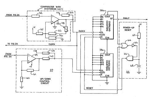
This motor overload circuit allows for short-term overdriving of a system, which is dependent on heat buildup. An overload detection circuit safeguards the motor against currents exceeding the rated current for specific exposure durations. The permissible exposure times are...
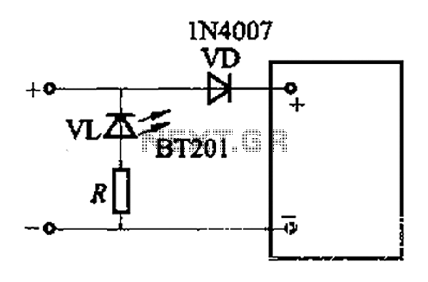
The adjustment potentiometer RP allows for modification of the over-voltage limit setting. In the event of reversed polarity in the DC power supply, there is a risk of damaging equipment components. To mitigate this risk, a reverse polarity protection...
This regulated power supply was built as a simplified outboard version of a PSU in my first phono stage. Replacing hexfreds with tube rectifier eliminates the need for power-on sequencing. Chassis (salvaged from a hospital laser PSU) size is...
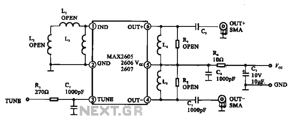
A low phase noise voltage-controlled oscillator circuit is presented, specifically integrated within the MAX2605-2609 voltage-controlled oscillator series. The circuit features a tuning voltage control terminal, allowing for adjustable oscillation frequency through a DC voltage input. The output of the...
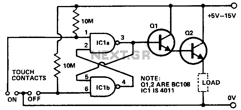
Touching the on contacts with a finger brings pin 3 high, turning on the Darlington pair and supplying power to the load (transistor radio, etc.). Q1 must be a high-gain transistor, and Q2 is chosen for the current required...
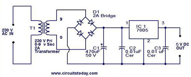
A 5V power supply using IC 7805 is designed and explained with a neat circuit diagram. The circuit for a 5V power supply utilizing the IC 7805 voltage regulator is a straightforward and efficient design that provides a stable output...